Showing posts with label interference. Show all posts

20200312

Physics quiz archive: interference, electrostatics

Physics 205B Quiz 3, spring semester 2020
Cuesta College, San Luis Obispo, CA
Sections 30882, 30883, version 1
Exam code: quiz03Cv1d


Sections 30882, 30883 results
0- 6 :  
7-12 :  
13-18 :   **** [low = 15]
19-24 :   ***************
25-30 :   *************** [mean = 24.2 +/- 4.2] [high = 30]

20190313

Physics quiz archive: interference, electrostatics

Physics 205B Quiz 3, spring semester 2019
Cuesta College, San Luis Obispo, CA
Sections 30882, 30883, version 1
Exam code: quiz03b3Am


Sections 30882, 30883 results
0- 6 :   ** [low = 3]
7-12 :   **
13-18 :   *********
19-24 :   ***************** [mean = 21.5 +/- 6.0]
25-30 :   ************ [high = 30]

20180307

Physics quiz archive: interference, electrostatics

Physics 205B Quiz 3, spring semester 2018
Cuesta College, San Luis Obispo, CA
Sections 30882, 30883, version 1
Exam code: quiz03Ch4R


Sections 30882, 30883 results
0- 6 :  
7-12 :   ** [low = 9]
13-18 :   ****
19-24 :   ************ [mean = 23.3 +/- 4.9]
25-30 :   ************** [high = 30]

20170311

Physics quiz archive: interference, electrostatics

Physics 205B Quiz 3, spring semester 2017
Cuesta College, San Luis Obispo, CA
Sections 30882, 30883, version 1
Exam code: quiz03d3St


Sections 30882, 30883 results
0- 6 :  
7-12 :   * [low = 9]
13-18 :   *****************
19-24 :   ******** [mean = 18.6 +/- 4.4]
25-30 :   ** [high = 27]

20160311

Physics quiz archive: interference, electrostatics

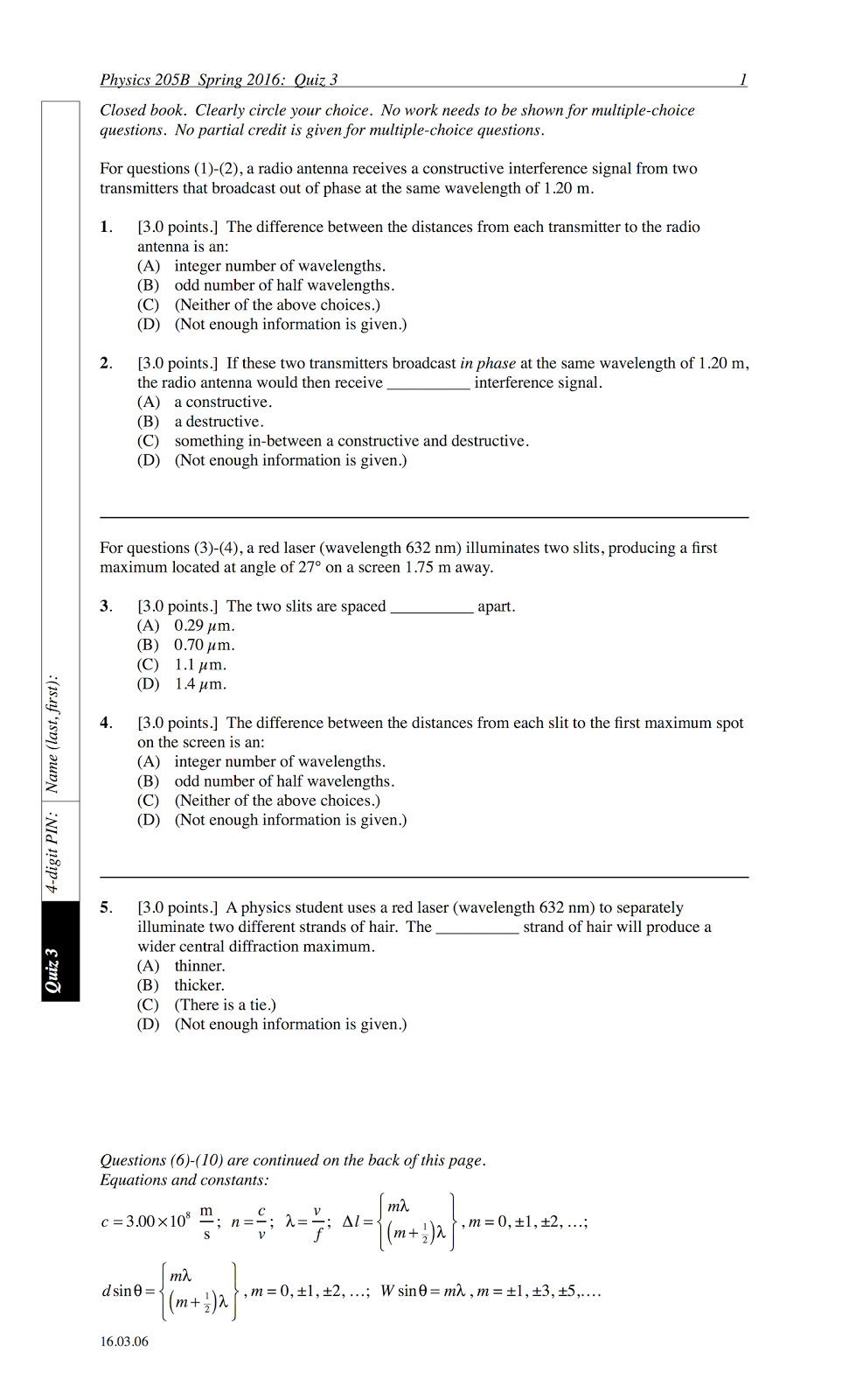
Physics 205B Quiz 3, spring semester 2016
Cuesta College, San Luis Obispo, CA
Sections 30882, 30883, version 1
Exam code: quiz03Ccf7


Sections 30882, 30883 results
0- 6 :   ** [low = 6]
7-12 :   ***********
13-18 :   ******
19-24 :   *************** [mean = 18.8 +/- 7.2]
25-30 :   ****** [high = 30]

20160226

Presentation: diffraction

Look at this fire hose nozzle. Just look at it. Pinching the flow of water makes it spread out more; while opening up the nozzle narrows the spread of water.

This is not meant to be a technically correct explanation for what we will see with waves that move through a single opening, but this very crude analogy will serve our purposes well enough.

Previously we considered the interference of waves from separate in phase sources, as monochromatic (same wavelength λ light) through two slits. Here we look at diffraction, which is the spread of light from a single slit.

First, terminology.

Notice how these parallel water wavefronts spread out after passing through the central opening in this inlet. This is an example of how waves diffract as they pass through a "single-slit" opening.

The relevant parameters are the wavelength λ of the parallel wavefronts and the slit opening width W, which affect how these waves diffract and spread out, given by the "half-angle" θ, as measured from the center line.

Second, quantifying the spread of these waves after diffracting through the singe slit.

If you squint (in order to increase the contrast of the diffracted wavefronts), you can make out a faint destructive region on either side of the center line, which forms the boundary of most of the diffracted wave energy. This is the first minima angle θ.

For our purposes will not derive this equation, as this would demand a non-trivial amount of calculus, or a very non-trivial end-run around calculus using qualitative arguments.
The equation for this diffraction minima is given by Wsinθ = mλ, where θ is the "half-angle" of the spread of the diffracted waves, and m = 1 (which if this doesn't freak you out by the resemblance to the double-slit maxima equation, it should). Just work with this, and let's see what it can tell us.

Much like constricting the nozzle would spread out the flow of water--but remember that this is nothing more than an analogy, and has no explanative power than reproducing the same result.
Since the slit width W and spread half-angle θ appear on both sides of the first diffraction minima equation, then making the slit opening smaller would result in increasing the spread of the diffracted waves.

Also making the slit opening larger would result in decreasing the spread of the diffracted waves.

An example of this is the diffraction of light through the circular aperture of a telescope with a "width" W (although the more correct equation in this case would have a correction for a diameter of a circular opening: Wsinθ = (1.22)(1)λ). This is the Whirlpool Galaxy M51 as seen by the NASA Spitzer Space Telescope and the European Space Agency Herschel Space Telescope, as observed with the same infrared wavelength λ. As the Spitzer Space Telescope has a much smaller mirror diameter, light from each part of the galaxy will diffract more and spread out more, resulting in a much less resolved image than from the Herschel Space Telescope, with a much larger mirror diameter, such that light from each part of the galaxy will diffract less and spread out less, resulting in a much better resolved image with finer details left intact.

Note the fainter fringes on either side of the central maximum 'spread.'
In laboratory you will shine a laser on your hair. Since the lasers are relatively low-powered (but don't shine them in your eyes), you won't be able to burn through your hairs, but light will diffract around either side of the hair shaft. This turns out to be entirely equivalent to light shining through a single slit of the same width as your hair, and the resulting diffraction pattern on a distant screen shows the spread of light contained within the first minima θ angles on either side of the center line. Depending on how thick your hair is will determine how little (or much) light will diffract and spread out on the screen.

20160223

Presentation: double-slit interference

Here we have microwaves (as discussed previously, a long wavelength form of electromagnetic radiation) from two side-by-side in-phase sources, interfering at a detector that can be moved at various locations to detect their interference, whether constructive or destructive (as translated into an audio signal). (Video link: "MIT Physics Demo--Microwave Interference.")

In the previous presentation we discussed the conditions for constructive or destructive interference for waves (of the same wavelength) due to phase and/or path differences. In this presentation we discuss the very specific case of waves (again, of the same wavelength) from two side-by-side in-phase sources, which we will see has been classically called "double-slit" interference.

First, path-length differences.

The waves we are considering will come from two sources that are in phase, so we do not need to concern ourselves with the out of phase sources. Since source phase differences don't matter here--only path differences--then we must pay careful attention to the difference in path length: how much longer the wave from one source travels than the wave from the other source, as they reach and interfere at the position of the detector, as it moves from side-to-side.

We are going to make the assumption that the detector is sufficiently (approaching infinitely?) far away from the two sources (spaced apart by a distance d) that the two waves will travel along a parallel path 1 and path 2. Then the location of the detector can be specified merely by the angle θ (where θ = 0° would be on the center line).

In this case, for the angle θ shown, waves travel longer along path 2. How much longer the waves travel along this longer path can be given by the relation ∆l = dsinθ. (There is a trigonometry derivation using the right triangle for this relation, but the focus here is on relating ∆l with the resulting constructive interference (maxima) or destructive interference (minima), and later on during problem-solving we'll use the ∆l = dsinθ relation to find these maxima and minima θ angles, without worrying too much about how to derive this ∆l = dsinθ relationship.)

Here's the simple case (θ = 0°) where both waves leave their slits to travel equal distances to the distant detector towards the right. Do the waves start from their slits in phase or out-of-phase? Is the path difference a whole wavelength or a half-wavelength? Does constructive interference (maxima) or destructive interference (minima) occur at the detector?

In this case, both waves leave their slits to travel unequal distances to the distant detector towards the right, located at an angle of θ = +23° off the (dashed) center line, such that path 1 is shorter than path 2. Do the waves start from their slits in phase or out-of-phase? Is the path difference a whole wavelength or a half-wavelength? Does constructive interference (maxima) or destructive interference (minima) occur at the detector? What would happen if the detector were instead placed at θ = –23° (same angle but on the other side of the center line)?

Now in this case, both waves leave their slits again to travel unequal distances to the distant detector towards the right, located at an angle of θ = –51° off the (dashed) center line, such that path 1 is longer than path 2. Do the waves start from their slits in phase or out-of-phase? Is the path difference a whole wavelength or a half-wavelength? Does constructive interference (maxima) or destructive interference (minima) occur at the detector? What would happen if the detector were instead placed at θ = +51° (same angle, but on the other side of the center line)?

Second, where we are going with this path-length difference relation: locating where these two sources interfere constructive (maxima) or destructively (minima).

As discussed before, for in phase sources, the difference in path length will be some integer m multiple of a wavelength for constructive interference, or will be some integer and a half (m + 1/2) multiple of wavelength for destructive interference.

So now let's put in our approximation for the path difference ∆l = dsinθ, for two waves from side-by-side sources reaching a (distant) detector located at an angle θ. What we will wind up with is a relation between the angle θ that a distant detector is located at, and the condition for either constructive (maxima) or destructive (minima) interference to occur. So given the wavelength λ of the two side-by-side sources, and the separation distance d between the two side-by-side sources, then plugging in different integer m values (0, ±1, ±2, ±3, etc.) allows us to solve for different θ angles where either constructive (maxima) or destructive (minima) interference occurs.

You will demonstrate this for yourselves in recreating a classic experiment in laboratory. Using laser light (of a given wavelength λ) that illuminates two very closely spaced together slits (two in-phase sources spaced a distance d apart), there will appear bright (maxima, or constructive interference) regions and dark (minima, or destructive interference) regions on a screen (the detector) at certain θ angles, as predicted by the double-slit interference maxima/minima equations.

20150314

Physics quiz archive: interference, electrostatics

Physics 205B Quiz 3, spring semester 2015
Cuesta College, San Luis Obispo, CA
Sections 30882, 30883, version 1
Exam code: quiz03wJnb


Sections 30882, 30883 results
0- 6 :   ****** [low = 0]
7-12 :   *****
13-18 :   ****************** [mean = 16.7 +/- 7.2]
19-24 :   ***********
25-30 :   **** [high = 30]

20140312

Physics quiz archive: interference, electrostatics

Physics 205B Quiz 3, spring semester 2014
Cuesta College, San Luis Obispo, CA
Sections 30882, 30883, version 1
Exam code: quiz03cDvD


Sections 30882, 30883 results
0- 6 :
7-12 : *** [low = 9]
13-18 : *******************
19-24 : ************* [mean = 19.7 +/- 5.0]
25-30 : ***** [high = 30]

20130313

Physics quiz archive: interference, electrostatics

Physics 205B Quiz 3, spring semester 2013
Cuesta College, San Luis Obispo, CA
Section 30882, version 1
Exam code: quiz03rD1o


Section 30882 results
0- 6 :
7-12 : ****** [low = 9]
13-18 : ********
19-24 : ************* [mean = 19.9 +/- 5.5]
25-30 : ***** [high = 30]

20130126

Presentation: interference

And he has a butler.
This is your neighbor. You know, the guy who plays his stereo system way too loud. (Video link: "Maxell Tape: Blown Away (1979).")
Butler: "The usual sir?"
Blown Away Guy: "Please."
(Tape player starts blaring Richard Wagner's Walkürenritt ("Ride of the Valkyries").)
Narrator: "Even after 500 plays, our high-fidelity tape still delivers...high fidelity."
Nobody who plays cassette tapes over a two-channel sound system deserves to crank up the volume.
Maybe we can do something about that, next time we just happen to be in his apartment (invited or not), with some minor adjustments to his stereo system wiring.

Last semester we discussed the behavior of sound waves, and so far this semester have been extending those concepts to model the behavior of electromagnetic radiation. Here we specifically look at the superposition of two waves in general, first sound, then later extending these concepts to visible light in a subsequent presentation.

First, defining a few terms.

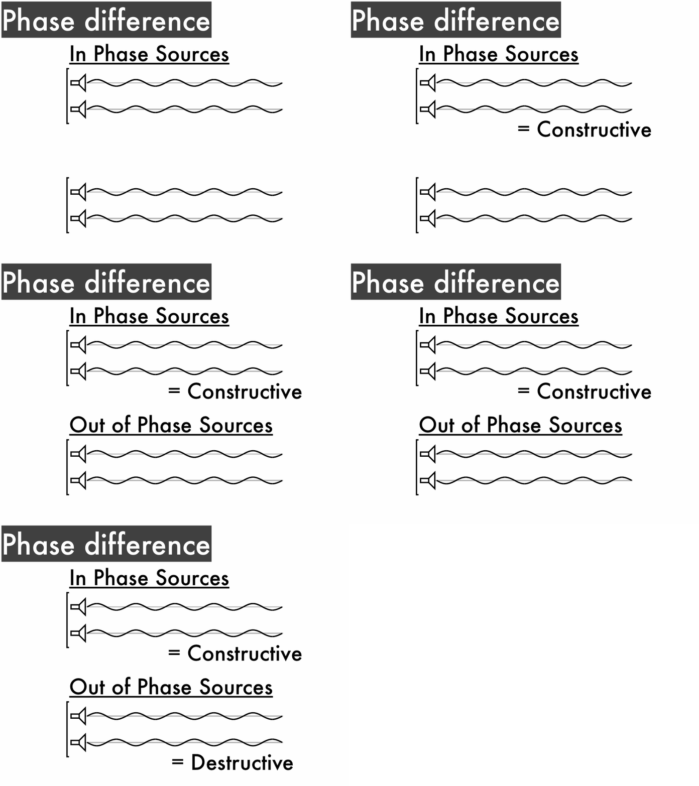
Here we have two speakers, which are our sources of two sound waves. Since they are plugged into the same frequency source, they will generate sound waves of the same frequency f (which is depends only on the source), same speed v (which depends only on the medium), and thus the same wavelength λ (which depends on both f and v). If the speakers are wired the same way--red and black wires to red and black plugs--then they will oscillate in phase, with both speaker cones moving forward and backwards in unison.

However, if the speakers are wired with opposite polarities--here, the speaker on the left is wired with black and red wires to red and black plugs--then they will oscillate out of phase, with one speaker cone moving backwards while the other is moving forwards, and then forwards while the other is moving backwards.

When we have two in phase sound sources with speaker cones that move in unison with each other, then the waves they generate will have crests and troughs that line up with each other. The superposition of these two waves will result in constructive interference, which will be a single louder wave.

If instead we have two out of phase sources with speaker cones that move contrary to each other, then the waves they generate will have crests and troughs that line up with the other speaker's troughs and crests. The superposition of these two waves will result in destructive interference--which would ideally be silence--but more realistically would be a single wave that is much quieter. (This is what would result if you switched the speaker wire polarities for one side of your neighbor's stereo system.)

Now let's consider two in phase sound speakers, but for an observer located at a position where the distance from each speaker--the path length--is different.

Here waves from the left speaker travel approximately 0.81 m, while the path length for the waves from the right speaker is about 0.63 m. The path differencel is the (absolute value) of how much farther one wave travels than the other, so in this case ∆l = 0.81 m - 0.63 m = 0.18 m.

This is why you should sit in the 'sweet spot,' equally distant from both speakers in order to minimize any path differences that may cause destructive interference.
Even with in phase speakers we can get either constructive or destructive interference, if the waves from each speaker travel different path lengths, resulting in certain path differences ∆l. For two in phase speakers where one wave travels a half-wavelength longer than the other, the path difference is (1/2)λ, and as a result crests and troughs line up with the other speaker's troughs and crests: destructive interference.

For two in phase speakers where one wave travels a whole wavelength longer than the other, the path difference is λ, and as a result crests and troughs line up with the other speaker's crests and troughs: constructive interference.

Second, mixing up the source phases and path difference conditions for constructive and destructive interference.

Here are two cases where both source phases and path differences matter. The top example is where two sources with a half-wavelength path difference results in constructive interference. The bottom example is where two sources with a whole wavelength path difference results in destructive interference. So how can we account for cases like these?

Whether constructive or destructive interference occurs depends on both the sources (how the waves start out, whether in phase or out of phase) and the path difference ∆l (how far each wave travels farther than the other, whether a whole wavelength or a half-wavelength longer than the other). There are four different cases:
  • For two in phase sources, if each wave travels a whole wavelength longer than the other, then constructive interference occurs (this is the solid black line.)
  • For two in phase sources, if each wave travels a half-wavelength longer than the other, then destructive interference occurs (this is the dashed black line.)
  • For two out of phase sources, if each wave travels a whole wavelength longer than the other, then destructive interference occurs (this is the solid red line.)
  • For two out of phase sources, if each wave travels a half-wavelength longer than the other, then constructive interference occurs (this is the dashed red line.)
Right now these different conditions look rather intimidating, so we'll make sure to be able to practice applying these conditions to various scenarios of in phase sources and out of phase sources with different shifted positions. Remember, there are only four unique cases of different phases and path differences.