Showing posts with label emf. Show all posts

20190510

Physics midterm problem: brightness of light bulbs in circuit

Physics 205B Midterm 2, spring semester 2019
Cuesta College, San Luis Obispo, CA

An ideal 9.0 V emf source is connected to several light bulbs that all have the same resistance. Calculate the powers dissipated (in watts) for each of these light bulbs. Show your work and explain your reasoning using Kirchhoff's rules, Ohm's law, and properties of electrical power.

Solution and grading rubric:
  • p:
    Correct. Solves for the powers dissipated by each light bulb by:
    1. finding equivalent resistance of the circuit by recognizing that the top light bulb is in series to the lower three parallel light bulbs);
    2. applying Ohm's law to determine the current of the equivalent circuit, which is the current flowing through the top light bulb;
    3. determines the power dissipated by the top light bulb;
    4. applies Kirchhoff's loop and/or junction rules to solve for the voltage difference used by and/or the current flowing through each of the lower three parallel light bulbs; and
    5. determines the power dissipated by each of the lower three parallel light bulbs.
  • r:
    Nearly correct, but includes minor math errors. Typically incorrect calculation in (1) or in (5), but otherwise everything else is consistent with this error.
  • t:
    Nearly correct, but approach has conceptual errors, and/or major/compounded math errors. Multiple issues in (1)-(5), but still attempts to systematically analyze most of (1)-(5) even with wrong numerical values.
  • v:
    Implementation of right ideas, but in an inconsistent, incomplete, or unorganized manner. Some attempt at applying Kirchhoff's rules, Ohm's law, and properties of electrical power.
  • x:
    Implementation of ideas, but credit given for effort rather than merit. No clear attempt at applying Kirchhoff's rules, Ohm's law, and properties of electrical power.
  • y:
    Irrelevant discussion/effectively blank.
  • z:
    Blank.
Grading distribution:
Sections 30882, 30883
Exam code: midterm02u7aH
p: 10 students
r: 6 students
t: 7 students
v: 18 students
x: 2 students
y: 0 students
z: 0 students

A sample "p" response (from student 1982):

Another sample "p" response (from student 8812):

20190422

Physics quiz archive: circuits (2)

Physics 205B Quiz 5, spring semester 2019
Cuesta College, San Luis Obispo, CA
Sections 30882, 30883, version 1
Exam code: quiz05eXpL


Sections 30882, 30883 results
0- 6 :  
7-12 :   ** [low = 9]
13-18 :   ****************
19-24 :   ***************** [mean = 20.2 +/- 4.7]
25-30 :   **** [high = 30]

20190410

Physics quiz archive: capacitors, circuits

Physics 205B Quiz 4, spring semester 2019
Cuesta College, San Luis Obispo, CA
Sections 30882, 30883, version 1
Exam code: quiz04KhhF


Sections 30882, 30883 results
0- 6 :  
7-12 :   **** [low = 9]
13-18 :   *****
19-24 :   *************** [mean = 23.4 +/- 6.0]
25-30 :   ***************** [high = 30]

20180416

Physics quiz archive: circuits (2)

Physics 205B Quiz 5, spring semester 2018
Cuesta College, San Luis Obispo, CA
Sections 30882, 30883, version 1
Exam code: quiz05z0m6


Sections 30882, 30883 results
0- 6 :  
7-12 :   ***** [low = 9]
13-18 :   *************** [mean = 18.4 +/- 4.4]
19-24 :   ******************* [high = 24]
25-30 :  

20180328

Physics quiz archive: capacitors, circuits

Physics 205B Quiz 4, spring semester 2018
Cuesta College, San Luis Obispo, CA
Sections 30882, 30883, version 1
Exam code: quiz04Md1o


Sections 30882, 30883 results
0- 6 :  
7-12 :   *** [low = 9]
13-18 :   ************
19-24 :   ************ [mean = 20.3 +/- 5.3]
25-30 :   ***** [high = 27]

20170507

Physics midterm problem: pencil lead variable resistor

Physics 205B Midterm 2, spring semester 2017
Cuesta College, San Luis Obispo, CA

A real battery with an emf of 6.0 V and an internal resistance of r = 1.2 Ω is attached to an ideal voltmeter, and is connected to an ideal ammeter and a pencil lead that acts as a variable resistor. If the amount of pencil lead between the contacts is shortened such that its resistance is reduced from 8.0 Ω to 1.0 Ω, discuss why the voltmeter reading will decrease while the ammeter reading will increase. Show your work and explain your reasoning using Kirchhoff's rules, Ohm's law, and properties of ammeters and voltmeters.

Solution and grading rubric:
  • p:
    Correct. Explains why the voltmeter reading will decrease while the ammeter reading will increase as the amount of pencil lead between the contacts is shortened by discussing:
    1. the decrease in the resistance of the pencil lead resistor will reduce the equivalent resistance of the circuit (pencil lead and internal resistance are in series), such that from applying Ohm's law the amount of current passing everywhere through the circuit will increase, resulting in a higher ammeter reading; and
    2. the voltmeter measures the potential difference of the 6.0 V rise from the emf and the voltage drop Ir from the internal resistance, such that an increase in current will result in a lower voltage reading ΔV = +ε − Ir.
  • (May instead discuss how the voltmeter is equivalently measuring the voltage drop ΔV = −IR across the pencil lead resistor, but must clearly show that the eight-fold decrease in the resistance (from 8.0 Ω to 1.0 Ω) will be larger than the corresponding approximate four-fold increase in current (0.65 A to 2.7 A) to result in a lower voltage reading.)
  • r:
    Nearly correct, but includes minor math errors.
  • t:
    Nearly correct, but approach has conceptual errors, and/or major/compounded math errors. At least numerically or qualitatively demonstrates how current would increase, but does not definitely show why voltmeter reading would decrease.
  • v:
    Implementation of right ideas, but in an inconsistent, incomplete, or unorganized manner. Some attempt at applying Kirchhoff's rules, Ohm's law, and equivalent resistance.
  • x:
    Implementation of ideas, but credit given for effort rather than merit. Approach other than that of applying Kirchhoff's rules, Ohm's law, and properties of ammeters and voltmeters.
  • y:
    Irrelevant discussion/effectively blank.
  • z:
    Blank.
Grading distribution:
Sections 30882, 30883
Exam code: midterm02GruT
p: 12 students
r: 0 students
t: 8 students
v: 8 students
x: 1 student
y: 0 students
z: 0 students

A sample "p" response (from student 1412):

Another sample "p" response (from student 2643):

A sample "x" response (from student 9319):

20170415

Physics quiz archive: circuits (2)

Physics 205B Quiz 5, spring semester 2017
Cuesta College, San Luis Obispo, CA
Sections 30882, 30883, version 1
Exam code: quiz05vLeY


Sections 30882, 30883 results
0- 6 :   *** [low = 3]
7-12 :   ****
13-18 :   ******* [mean = 17.7 +/- 7.0]
19-24 :   *********
25-30 :   *** [high = 27]

20170331

Physics quiz archive: capacitors, circuits

Physics 205B Quiz 4, spring semester 2017
Cuesta College, San Luis Obispo, CA
Sections 30882, 30883, version 1
Exam code: quiz04Br7w


Sections 30882, 30883 results
0- 6 :  
7-12 :   ******* [low = 9]
13-18 :   ******** [mean = 17.1 +/- 5.4]
19-24 :   ******
25-30 :   ** [high = 30]

20160508

Physics midterm problem: change in voltmeter reading

Physics 205B Midterm 2, spring semester 2016
Cuesta College, San Luis Obispo, CA

A "AA" alkaline battery with an emf of 1.5 V and an internal resistance of r = 0.90 Ω is attached to an ideal voltmeter, with a R = 2.0 Ω light bulb that is wired in parallel with an open switch. Discuss why the voltmeter will have a lower reading after the switch is closed. Show your work and explain your reasoning using Kirchhoff's rules, Ohm's law, and properties of voltmeters.

Solution and grading rubric:
  • p:
    Correct. Recognizes that when the switch is open, the voltmeter will have a non-zero reading, and have a lower (zero) reading when the switch is closed, using one of two similar arguments:
    1. when the switch is open, there is a non-zero ΔV = +1.5 V − Ir reading, and when the switch is closed, from Kirchhoff's loop rule the voltage rise of +1.5 V from the emf must now exactly equal the −Ir voltage drop of the internal resistance of the battery, such that the voltmeter reading is now zero; or
    2. when the switch is open, there is a non-zero ΔV = − IR reading, and when the switch is closed, since the light bulb R is bypassed by a zero resistance switch, making ΔV = 0.
  • r:
    Nearly correct, but includes minor math errors. Does not sufficiently show numerically or qualitatively how voltmeter reading when switch is open is higher versus when the switch is closed.
  • t:
    Nearly correct, but approach has conceptual errors, and/or major/compounded math errors. At least has a conceptual understanding of how a voltmeter measures a potential difference, and how the switch changes the current flow when it is open versus when it is closed.
  • v:
    Implementation of right ideas, but in an inconsistent, incomplete, or unorganized manner. Some attempt at applying Kirchhoff's rules, Ohm's law, and equivalent resistance.
  • x:
    Implementation of ideas, but credit given for effort rather than merit. Approach other than that of applying Kirchhoff's rules, Ohm's law, and properties of voltmeters.
  • y:
    Irrelevant discussion/effectively blank.
  • z:
    Blank.
Grading distribution:
Sections 30882, 30883
Exam code: midterm02Mc4s
p: 7 students
r: 17 students
t: 4 students
v: 12 students
x: 2 students
y: 0 students
z: 0 students

A sample "p" response (from student 3158):

Another sample "p" response (from student 5433):

20160417

Physics quiz archive: circuits (2)

Physics 205B Quiz 5, spring semester 2016
Cuesta College, San Luis Obispo, CA
Sections 30882, 30883, version 1
Exam code: quiz05Tt1p


Sections 30882, 30883 results
0- 6 :  
7-12 :   *** [low = 12]
13-18 :   **************
19-24 :   ************* [mean = 20.8 +/- 5.0]
25-30 :   ******** [high = 30]

20150512

Physics midterm problem: comparing voltmeter readings

Physics 205B Midterm 2, spring semester 2015
Cuesta College, San Luis Obispo, CA

Cf. Giambattista/Richardson/Richardson, Physics, 2/e, Problem 18.72

Two voltmeters are connected to circuit with a switch, a light bulb, a resistor, and an emf source. All of these components are ideal. The resistance R of the resistor is greater than the resistance r of the light bulb. The top and bottom voltmeters have the same reading while the switch is open. Discuss why the top and bottom voltmeters will have different readings after the switch has been closed. Show your work and explain your reasoning using Kirchhoff's rules, Ohm's law, and properties of voltmeters.

Solution and grading rubric:
  • p:
    Correct. Understands that closing the switch would allow current to flow through the emf, resistor and light bulb series circuit, while completely by-passing the lower voltmeter, such that:
    1. the upper voltmeter would read a non-zero voltage difference of ΔV = +ε – IR (or equivalently, ΔV = (–)Ir); and
    2. the lower voltmeter would read zero, as there is no voltage drop due to the ideally zero resistance switch.
  • r:
    Nearly correct, but includes minor math errors. Understands that current will now flow through the circuit, but does not give correct reading of one of the voltmeters, but has correct reading for the other.
  • t:
    Nearly correct, but approach has conceptual errors, and/or major/compounded math errors. Understands that current will now flow through the circuit, but does not give correct readings for both voltmeters.
  • v:
    Implementation of right ideas, but in an inconsistent, incomplete, or unorganized manner. At least understands that current will now flow through the circuit.
  • x:
    Implementation of ideas, but credit given for effort rather than merit. Approach other than that of applying Kirchhoff's rules, Ohm's law, and properties of voltmeters.
  • y:
    Irrelevant discussion/effectively blank.
  • z:
    Blank.
Grading distribution:
Sections 30882, 30883
Exam code: midterm02m3tR
p: 8 students
r: 15 students
t: 7 students
v: 14 students
x: 3 students
y: 0 students
z: 0 students

A sample "p" response (from student 9178):

20150418

Physics quiz archive: circuits (2)

Physics 205B Quiz 5, spring semester 2015
Cuesta College, San Luis Obispo, CA
Sections 30882, 30883, version 1
Exam code: quiz05aL7y


Sections 30882, 30883 results
0- 6 :   * [low = 6]
7-12 :   ****
13-18 :   **********************
19-24 :   ************* [mean = 19.0 +/- 5.5]
25-30 :   ******* [high = 30]

20150403

Physics quiz archive: capacitors, circuits

Physics 205B Quiz 4, spring semester 2015
Cuesta College, San Luis Obispo, CA
Sections 30882, 30883, version 1
Exam code: quiz04sm7H


Sections 30882, 30883 results
0- 6 :   ****** [low = 0]
7-12 :   *********
13-18 :   **************** [mean = 15.4 +/- 7.0]
19-24 :   ***********
25-30 :   ** [high = 30]

20150311

Presentation: circuit basics

Wet plywood. Wires clipped to nails. Wires connected to a source of 15,000 volts. What could be more beautiful than this basic circuit? Or dangerous? (Video link: 15,000 volts.")

In this presentation we will take a first look at the basics of basic circuits. As with the set-up above, some of these very basic circuits are also very dangerous, so unless you absolutely know what you're doing (that is to say, you know enough physics to understand the perils involved), do not try these at home!

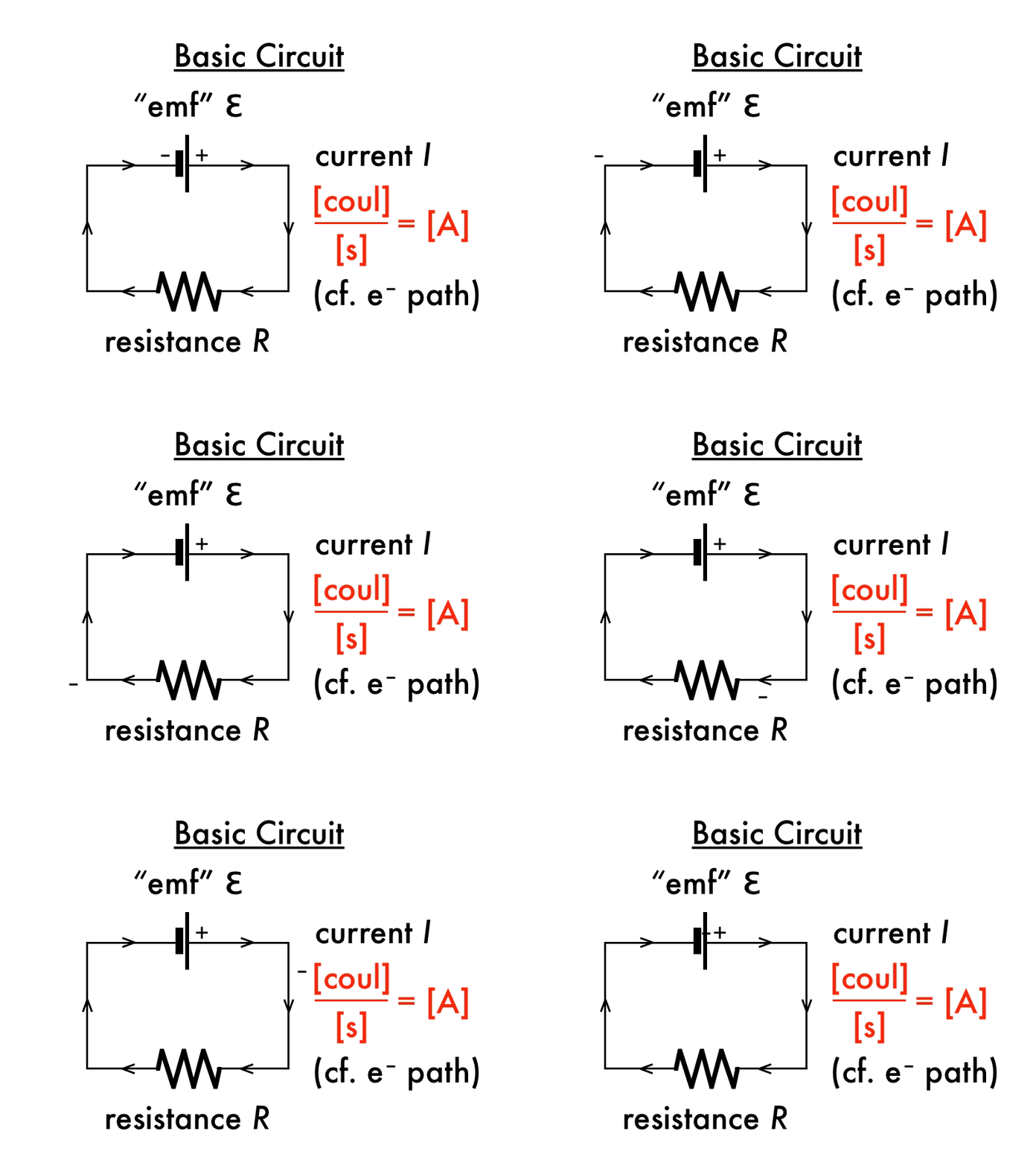
The most basic circuit we can build will have an ideal "electromotive" (emf) source of voltage connected to a resistor, such that charges can flow continuously around and around. Peculiarly the definition of current is the amount of positive charge (in coulombs (C)) that circulates per time (in seconds (s)), and these units of C/s are defined as amps (A). But as discussed in a previous presentation, in a conductor it is actually the negatively charged electrons that are free to move. So by convention we refer to "current" flowing clockwise through this circuit, while the electrons actually circulate in the opposite counterclockwise direction through this circuit. Just keep watching this GIF animation for a while until you get used to those current direction concepts. More on emf sources and resistors below, when you're ready.

An ideal battery uses chemical reactions that exchange charges in order to release electric potential energy, giving potential (that is, electric potential energy per charge, or voltage, measured in volts (V)) to the charges that circulate in a circuit.

Different chemical reactions will release different amounts of electric potential energy per charge, and thus different amounts of voltage. Note that these different batteries all have the same "AA" size, but the different chemical reactants inside (nickel metal hydride (NiMh), alkaline, or lithium) release different amounts of voltage (∆V = 1.2 V, 1.5 V, or 3.6 V, respectively). (Ideally the amount of voltage provided will be constant; but later we'll consider the effects of depleting the reactants inside "real" batteries, and the effect this has on their actual voltage output over time.)

Some larger voltage batteries are made up of a combination of individual batteries, in order to "stack" the voltage output ∆V, which is cumulative provided that their terminals are connected (+) to (-), etc. The result of stacking six individual 1.5 V alkaline batteries results in a single 9.0 V battery, as seen in several different stacking configurations.

The other part of a basic circuit is a resistor, which uses up voltage (electric potential energy per charge) as current flows through it. Different types of materials and shapes and sizes will result in different resistance values, measured in ohms (Greek letter Ω). (This is the inverse of conductance, so a good conductor (such as a metal wire) will have a low resistance value, while a poor conductor (such as an insulator) will have a high resistance value.)

If several resistors (here, Christmas light bulbs) are strung together in a line, forcing current to flow through each one in turn, then the equivalent resistance is their individual resistances added together. (This is not the only possible way to wire together resistors, but we'll stick to this basic configuration for now.)

Ohm's law can be applied to a basic circuit to determine how much current will flow in it, given the total amount of voltage from ideal batteries, and the equivalent resistance of all the resistors. Note how the different units are related in Ohm's law: a volt over an ohm is equivalent to an ampere, etc. (After a certain point you will just have to trust that all these units will work out in the end.)

So let's look at some very basic, very dangerous circuits.

We can use a wire (which has a very low resistance) to complete a basic circuit, connecting it to the (+) and (-) terminals of a 9.0 V (ideal) battery. Note the very small spark of current that leaps across the gap just as the wire completes the circuit. Now an absurd configuration of 244 9.0 V batteries are stacked with (+) terminals to (-) terminals. (How much emf voltage is that?) When a wire is connected to complete this stacked battery circuit, how does the amount of emf voltage compare to the single 9.0 V battery circuit? How does the amount of current compare to the single 9.0 V battery circuit? (Video source: "Fun with a few 9V batteries. (244 of them).")

Our next very dangerous basic circuit involves deionized water, itself a relatively poor conductor, as there are no free charges in it to transport current, so connecting a basic circuit of water with a household 120 V outlet as an emf source (where the light bulb is used to indicate the amount of current that is flowing) doesn't yield much current. When salt is poured into the water, introducing charged sodium (Na+) and chloride (Cl-) ions, how did the amount of resistance of this circuit change? How did the amount of current through this circuit change? (Video source: "Experiment electricity with saltwater.")

Our last very dangerous basic circuit is a power transformer used as an emf source, with a metal screw used to complete the circuit. This will result in a "short circuit," which is due to a very large or very small resistance? Does a very large or very small current result? (Video source: "The Metal Melter.")

In subsequent presentations we will go over more specific rules of circuit analysis for more complex configurations of emf sources and resistors, and power dissipation.