Showing posts with label voltage. Show all posts

20190510

Physics midterm problem: brightness of light bulbs in circuit

Physics 205B Midterm 2, spring semester 2019
Cuesta College, San Luis Obispo, CA

An ideal 9.0 V emf source is connected to several light bulbs that all have the same resistance. Calculate the powers dissipated (in watts) for each of these light bulbs. Show your work and explain your reasoning using Kirchhoff's rules, Ohm's law, and properties of electrical power.

Solution and grading rubric:
  • p:
    Correct. Solves for the powers dissipated by each light bulb by:
    1. finding equivalent resistance of the circuit by recognizing that the top light bulb is in series to the lower three parallel light bulbs);
    2. applying Ohm's law to determine the current of the equivalent circuit, which is the current flowing through the top light bulb;
    3. determines the power dissipated by the top light bulb;
    4. applies Kirchhoff's loop and/or junction rules to solve for the voltage difference used by and/or the current flowing through each of the lower three parallel light bulbs; and
    5. determines the power dissipated by each of the lower three parallel light bulbs.
  • r:
    Nearly correct, but includes minor math errors. Typically incorrect calculation in (1) or in (5), but otherwise everything else is consistent with this error.
  • t:
    Nearly correct, but approach has conceptual errors, and/or major/compounded math errors. Multiple issues in (1)-(5), but still attempts to systematically analyze most of (1)-(5) even with wrong numerical values.
  • v:
    Implementation of right ideas, but in an inconsistent, incomplete, or unorganized manner. Some attempt at applying Kirchhoff's rules, Ohm's law, and properties of electrical power.
  • x:
    Implementation of ideas, but credit given for effort rather than merit. No clear attempt at applying Kirchhoff's rules, Ohm's law, and properties of electrical power.
  • y:
    Irrelevant discussion/effectively blank.
  • z:
    Blank.
Grading distribution:
Sections 30882, 30883
Exam code: midterm02u7aH
p: 10 students
r: 6 students
t: 7 students
v: 18 students
x: 2 students
y: 0 students
z: 0 students

A sample "p" response (from student 1982):

Another sample "p" response (from student 8812):

20190501

Physics quiz archive: magnetism, induction

Physics 205B Quiz 6, spring semester 2019
Cuesta College, San Luis Obispo, CA
Sections 30882, 30883, version 1
Exam code: quiz06riQ1


Sections 30882, 30883 results
0- 6 :  
7-12 :   ***** [low = 9]
13-18 :   ********
19-24 :   ************** [mean = 21.4 +/- 5.5]
25-30 :   *********** [high = 30]

20190422

Physics quiz archive: circuits (2)

Physics 205B Quiz 5, spring semester 2019
Cuesta College, San Luis Obispo, CA
Sections 30882, 30883, version 1
Exam code: quiz05eXpL


Sections 30882, 30883 results
0- 6 :  
7-12 :   ** [low = 9]
13-18 :   ****************
19-24 :   ***************** [mean = 20.2 +/- 4.7]
25-30 :   **** [high = 30]

20190416

Physics quiz archive: magnetism, induction

Physics 205B Quiz 6, spring semester 2018
Cuesta College, San Luis Obispo, CA
Sections 30882, 30883, version 1
Exam code: quiz06Av3g


Sections 30882, 30883 results
0- 6 :   * [low = 6]
7-12 :  
13-18 :   ************
19-24 :   ******************* [mean = 20.1 +/- 4.2]
25-30 :   ** [high = 27]

20190410

Physics quiz archive: capacitors, circuits

Physics 205B Quiz 4, spring semester 2019
Cuesta College, San Luis Obispo, CA
Sections 30882, 30883, version 1
Exam code: quiz04KhhF


Sections 30882, 30883 results
0- 6 :  
7-12 :   **** [low = 9]
13-18 :   *****
19-24 :   *************** [mean = 23.4 +/- 6.0]
25-30 :   ***************** [high = 30]

20180416

Physics quiz archive: circuits (2)

Physics 205B Quiz 5, spring semester 2018
Cuesta College, San Luis Obispo, CA
Sections 30882, 30883, version 1
Exam code: quiz05z0m6


Sections 30882, 30883 results
0- 6 :  
7-12 :   ***** [low = 9]
13-18 :   *************** [mean = 18.4 +/- 4.4]
19-24 :   ******************* [high = 24]
25-30 :  

20180328

Physics quiz archive: capacitors, circuits

Physics 205B Quiz 4, spring semester 2018
Cuesta College, San Luis Obispo, CA
Sections 30882, 30883, version 1
Exam code: quiz04Md1o


Sections 30882, 30883 results
0- 6 :  
7-12 :   *** [low = 9]
13-18 :   ************
19-24 :   ************ [mean = 20.3 +/- 5.3]
25-30 :   ***** [high = 27]

20170507

Physics midterm problem: pencil lead variable resistor

Physics 205B Midterm 2, spring semester 2017
Cuesta College, San Luis Obispo, CA

A real battery with an emf of 6.0 V and an internal resistance of r = 1.2 Ω is attached to an ideal voltmeter, and is connected to an ideal ammeter and a pencil lead that acts as a variable resistor. If the amount of pencil lead between the contacts is shortened such that its resistance is reduced from 8.0 Ω to 1.0 Ω, discuss why the voltmeter reading will decrease while the ammeter reading will increase. Show your work and explain your reasoning using Kirchhoff's rules, Ohm's law, and properties of ammeters and voltmeters.

Solution and grading rubric:
  • p:
    Correct. Explains why the voltmeter reading will decrease while the ammeter reading will increase as the amount of pencil lead between the contacts is shortened by discussing:
    1. the decrease in the resistance of the pencil lead resistor will reduce the equivalent resistance of the circuit (pencil lead and internal resistance are in series), such that from applying Ohm's law the amount of current passing everywhere through the circuit will increase, resulting in a higher ammeter reading; and
    2. the voltmeter measures the potential difference of the 6.0 V rise from the emf and the voltage drop Ir from the internal resistance, such that an increase in current will result in a lower voltage reading ΔV = +ε − Ir.
  • (May instead discuss how the voltmeter is equivalently measuring the voltage drop ΔV = −IR across the pencil lead resistor, but must clearly show that the eight-fold decrease in the resistance (from 8.0 Ω to 1.0 Ω) will be larger than the corresponding approximate four-fold increase in current (0.65 A to 2.7 A) to result in a lower voltage reading.)
  • r:
    Nearly correct, but includes minor math errors.
  • t:
    Nearly correct, but approach has conceptual errors, and/or major/compounded math errors. At least numerically or qualitatively demonstrates how current would increase, but does not definitely show why voltmeter reading would decrease.
  • v:
    Implementation of right ideas, but in an inconsistent, incomplete, or unorganized manner. Some attempt at applying Kirchhoff's rules, Ohm's law, and equivalent resistance.
  • x:
    Implementation of ideas, but credit given for effort rather than merit. Approach other than that of applying Kirchhoff's rules, Ohm's law, and properties of ammeters and voltmeters.
  • y:
    Irrelevant discussion/effectively blank.
  • z:
    Blank.
Grading distribution:
Sections 30882, 30883
Exam code: midterm02GruT
p: 12 students
r: 0 students
t: 8 students
v: 8 students
x: 1 student
y: 0 students
z: 0 students

A sample "p" response (from student 1412):

Another sample "p" response (from student 2643):

A sample "x" response (from student 9319):

20170429

Physics quiz archive: magnetism, induction

Physics 205B Quiz 6, spring semester 2017
Cuesta College, San Luis Obispo, CA
Sections 30882, 30883, version 1
Exam code: quiz06LnDr


Sections 30882, 30883 results
0- 6 :  
7-12 :  
13-18 :   ******** [low = 15]
19-24 :   ************** [mean = 21.8 +/- 4.1]
25-30 :   ******* [high = 30]

20170415

Physics quiz archive: circuits (2)

Physics 205B Quiz 5, spring semester 2017
Cuesta College, San Luis Obispo, CA
Sections 30882, 30883, version 1
Exam code: quiz05vLeY


Sections 30882, 30883 results
0- 6 :   *** [low = 3]
7-12 :   ****
13-18 :   ******* [mean = 17.7 +/- 7.0]
19-24 :   *********
25-30 :   *** [high = 27]

20170331

Physics quiz archive: capacitors, circuits

Physics 205B Quiz 4, spring semester 2017
Cuesta College, San Luis Obispo, CA
Sections 30882, 30883, version 1
Exam code: quiz04Br7w


Sections 30882, 30883 results
0- 6 :  
7-12 :   ******* [low = 9]
13-18 :   ******** [mean = 17.1 +/- 5.4]
19-24 :   ******
25-30 :   ** [high = 30]

20160508

Physics midterm problem: change in voltmeter reading

Physics 205B Midterm 2, spring semester 2016
Cuesta College, San Luis Obispo, CA

A "AA" alkaline battery with an emf of 1.5 V and an internal resistance of r = 0.90 Ω is attached to an ideal voltmeter, with a R = 2.0 Ω light bulb that is wired in parallel with an open switch. Discuss why the voltmeter will have a lower reading after the switch is closed. Show your work and explain your reasoning using Kirchhoff's rules, Ohm's law, and properties of voltmeters.

Solution and grading rubric:
  • p:
    Correct. Recognizes that when the switch is open, the voltmeter will have a non-zero reading, and have a lower (zero) reading when the switch is closed, using one of two similar arguments:
    1. when the switch is open, there is a non-zero ΔV = +1.5 V − Ir reading, and when the switch is closed, from Kirchhoff's loop rule the voltage rise of +1.5 V from the emf must now exactly equal the −Ir voltage drop of the internal resistance of the battery, such that the voltmeter reading is now zero; or
    2. when the switch is open, there is a non-zero ΔV = − IR reading, and when the switch is closed, since the light bulb R is bypassed by a zero resistance switch, making ΔV = 0.
  • r:
    Nearly correct, but includes minor math errors. Does not sufficiently show numerically or qualitatively how voltmeter reading when switch is open is higher versus when the switch is closed.
  • t:
    Nearly correct, but approach has conceptual errors, and/or major/compounded math errors. At least has a conceptual understanding of how a voltmeter measures a potential difference, and how the switch changes the current flow when it is open versus when it is closed.
  • v:
    Implementation of right ideas, but in an inconsistent, incomplete, or unorganized manner. Some attempt at applying Kirchhoff's rules, Ohm's law, and equivalent resistance.
  • x:
    Implementation of ideas, but credit given for effort rather than merit. Approach other than that of applying Kirchhoff's rules, Ohm's law, and properties of voltmeters.
  • y:
    Irrelevant discussion/effectively blank.
  • z:
    Blank.
Grading distribution:
Sections 30882, 30883
Exam code: midterm02Mc4s
p: 7 students
r: 17 students
t: 4 students
v: 12 students
x: 2 students
y: 0 students
z: 0 students

A sample "p" response (from student 3158):

Another sample "p" response (from student 5433):

20160430

Physics quiz archive: magnetism, induction

Physics 205B Quiz 6, spring semester 2016
Cuesta College, San Luis Obispo, CA
Sections 30882, 30883, version 1
Exam code: quiz06eL3k


Sections 30882, 30883 results
0- 6 :   *   [low = 6]
7-12 :   *****
13-18 :   *********************   [mean = 17.0 +/- 5.1]
19-24 :   **********
25-30 :   *   [high = 27]

20160417

Physics quiz archive: circuits (2)

Physics 205B Quiz 5, spring semester 2016
Cuesta College, San Luis Obispo, CA
Sections 30882, 30883, version 1
Exam code: quiz05Tt1p


Sections 30882, 30883 results
0- 6 :  
7-12 :   *** [low = 12]
13-18 :   **************
19-24 :   ************* [mean = 20.8 +/- 5.0]
25-30 :   ******** [high = 30]

20160304

Presentation: capacitors

Look at these capacitors. Just look at them. How dangerous could these be? One of them even looks like an M&M™...

Notice the smile on the woman at the end of the clip.
Well, maybe just a little dangerous, when embedded in protective clothing for self-protection purposes. But why? Are capacitors "shocking" because they store charge? Voltage? Energy? All three? (Video link: "No-Contact™ Conducted Energy Clothing.")

In this presentation we will look at the construction of capacitors, and how and what they "store."

First, the construction and charging of capacitors.

Even though capacitors come in many different shapes and sizes, carefully taking one apart will demonstrate certain common features. In the case of this cylindrical capacitor, after removing the casing, and unrolling its layers, there are two parallel metal sheets (here kept a fixed distance apart by an oil-impregnated sheet). (Video link: "MAKE presents: The Capacitor.")

The basic model of a capacitor is very similar, with two parallel metal plates of equal area A, held a fixed distance d apart. To keep things simple we assume that the space between the plates is air (or vacuum, although this space could be filled by an insulating liquid or solid "dielectric").

We can calculate the capacitance of a given parallel-plate capacitor from its area A and separation distance d. As the constant k has units of coulombs2 per joule (C2/J) that remain after canceling out the A and d units, we redefine the C2/J units of capacitance as farads (F).

The capacitance of a capacitor is fixed once it is constructed, as the only way to change the capacitance is to change its "build" parameters: the area A and/or the separation distance d.

Now let's charge up a capacitor. This is done by connecting the capacitor plates to a voltage source such as a battery, in order to create a potential difference (in volts). As discussed in a previous presentation, electrons are the only mobile charges in a conductor, so only they are free to move, while the positively charged atomic nuclei remain fixed. Each and every electron taken from the top plate makes the top plate increasingly positively charged, and each and every one of these electrons are eventually deposited onto the bottom plate, making the bottom plate increasingly negatively charged. After the capacitor is fully charged, no more electrons can be moved, and the top and bottom plate have the same final charge of +Q and –Q.

So just how much charge could a capacitor store on its plates? When does a capacitor "know" when to stop charging?

Capacitance is the key relation between how much potential difference (voltage) is applied to the plates, and how much charge will finally be stored.

(The units for charge (in coulombs, C) and potential (in volts, V; or joules/coulomb, J/C) again work out to coulombs2 per joule, or farads for the capacitance.)

The key is to realize that the capacitance of a capacitor, once built, is fixed. However, one can change the amount of potential applied to the capacitor (by connecting different batteries, etc.). With a given value of capacitance, then applying a high potential to the capacitor will allow it to store more charge, and applying a low potential to the capacitor will have it store less charge.

Thus capacitance can be said to be a measure of "charge-storing efficiency" with respect to a given potential, in that a large capacitance capacitor will store more charge than one with a small capacitance, if they are connected to the same potential source (such as a battery).

Capacitance is a critical parameter, as seen by disassembling a supposed ginormous 6,800 µF capacitor (which would store a lot of charge when connected to a given battery), and finding a cheaper 2,200 µF capacitor inside, which would store a lot less charge. What's up with that? ("KIRF" = "keeping it real fake.")

Second, storing electric potential energy in capacitors.

Let's watch a capacitor being charged, by applying a potential source to it (such as a battery), and watching the electrons removed from the top plate (making it positively charged) being deposited onto the bottom plate (making it negatively charged). Note how the first electron q travels quickly because it's "easy" to move, while the last electron q moves very slowly because it's "hard" to move.

The first electron q has a "start-up" energy cost of effectively zero, as it moved from and to plates that are nearly or effectively uncharged (and start with zero potential, such that ∆EPE = q·(0) = 0 J).

However, the last electron q must be removed from a very positively charged plate, which requires a lot of work, and also must be moved onto a very negatively charged plate, again requiring a lot of work (the difficulty of which is indicated by the slowness of moving this electron). Since the plates are at or nearly at their final potential value ∆V, the last electron q has an energy "end cost" of ∆EPE = q·∆V (don't worry about negative signs in this argument).

Thus the first electron moved costs nothing (or nearly nothing), while the last electron requires a much higher q·∆V cost to move. The average cost of moving each electron, then, can be said to be (1/2)·q·∆V, such that the total cost of moving all electrons is (1/2)·Q·∆V, where the total charge of all N electrons moved is Q = N·q. (This argument is deliberately trying to avoid calculus to integrate the gradually increasing cost of each electron over all electrons moved, but the result is the same.)

So capacitors store electric potential energy by storing a given amount of charge when connected to a potential source (such as a battery). With the C = Q/∆V relation, the two parameters Q and ∆V in the electric potential energy equation can each be substituted out, yielding two other equivalent equations for electric potential energy EPE.

Endless hours of amusement await you when solving capacitor energy problems, so use caution when you use these equations, and more importantly, use only the equation you really need.

As in shock-deterrent clothing, capacitors are used to store electric potential energy to be used at a later time, such as camera flashes and this cardiac defibrillator. Sure, when you get "shocked" by a capacitor, charges are coming off of the capacitor (and traveling through your body), but it is the electric potential energy carried by these charges that makes capacitors hazardous. And more importantly, a key advantage capacitors have over batteries in storing electric potential energy for later use, is that the energy from a capacitor can be released in a very brief amount of time (as opposed to a small steady amount over a long period of time), as we will see in a subsequent presentation.

Presentation: electric potential energy

Look at all these batteries. Just look at them. While we might think of them as "containing" electrical potential energy, or even as voltage "sources," we'll see that just two charges can "contain" electric potential energy, and that just a single charge can be thought of as a voltage "source." In subsequent presentations we'll explore more complex voltage "sources" that "contain" electric potential energy: capacitors, batteries, and household electric outlets.

In this presentation we will consider different approaches to analyze electric potential energy.

First, a direct approach to electric potential energy.

Recall that in the direct approach to electric forces, a source charge q1 can be said to exert a force F on a separate test charge q2.

Similarly, a direct approach to electric potential energy is that a source charge q1 can be said to store electric potential energy EPE on with a separate test charge charge q2.

EPE changes in this electric potential energy are caused by moving the source charge and test charge closer together, or moving them farther apart. EPE can be increased (thus making ∆EPE positive) by pushing together like-sign charges (positive-positive, or negative-negative), or pulling apart opposite-sign charges (positive-negative, or negative-postive). This is because it takes work to push together like-sign charges (which repel, and don't want to be pushed together); or takes work to pull apart opposite-sign charges (which attract, and don't want to be pulled apart).

On the other hand, work is done by charges that are allowed to do what they want to, thus decreasing EPE (and making ∆EPE negative), by letting like-sign charges (positive-positive, or negative-negative) move farther apart from each other (because these charges repel); or letting opposite-sign charges (positive-negative, or negative-positive) move closer to each other (because these charges attract).

The value of the electric potential energy of a source charge q1 and test charge q2 at a certain distance r from each other can be calculated by an equation that looks similar to the magnitude of the electric force (but note the r–1 dependence for electric potential energy, as opposed to the r-2 dependence of electric forces). With the constant k, units of coulombs2 and meters cancel, leaving units of N·m, which is what we have seen last semester as joules.

(Note that this equation calculates the value of electric potential energy EPE of two charges at a fixed separation distance from each other. In order to find the ∆EPE change in electric potential energy, you would need to calculate the initial EPEi and final EPEf electric potential energies of the two charges at their initial ri and final rf separation distances.)

Second, the two-step approach to electric potential energy.

Recall that in the two-step approach to electric forces, a source charge Q can be said to create an electric field E everywhere around itself, and then this electric field exerts a force F on a separate test charge q.

Similarly, a two-step approach to electric potential energy is that a source charge Q can be said to create a potential V everywhere around itself, and this potential stores electric potential energy EPE with a separate test charge charge q.

Let's focus on the first step of this two-step model. The source charge Q creates a potential V everywhere around it. The magnitude of this potential can be calculated for a location at a distance r from the source charge, and has units of joules per coulomb (J/C), which is often re-expressed as volts (V). The sign of the potential depends on the sign of the source charge Q: if the source charge is positive, then the values of the potential everywhere around it are positive; if the source charge is negative, then the values of the potential everywhere around it are negative.

Recall that electric fields surrounding a single source charge are visualized as lines emanating outwards from, or pointing in towards the source charge. In contrast, the potentials surrounding a single source charge are visualized (here, in two-dimensions) as circles, as every location at the same distance r from the source charge must have the same value of potential, such that these circles are often referred to as equipotentials.

Note that the direction of electric field lines is indicative of the relative values of the equipotentials: for the positive source charge, each subsequent outer equipotential corresponds to smaller and smaller positive values of potential (due to the r–1 dependence); for the negative source charge, each subsequent inner potential equipotential corresponds to larger and larger negative values of potential. So in either case, electric field lines point towards decreasing electric potential values.

A nice visualization is to imagine that a positive source charge creates a "peak" of potential around it--as you get closer in towards this positive source charge, the values of potential become bigger and bigger positive numbers, corresponding to a increase in elevation. In contrast, a negative source charge creates a "well" of potential around it--as you get closer in towards this negative source charge, the values of potential become bigger and bigger negative numbers, corresponding to a decrease in elevation.

So where does "voltage" come in? The amount of potential (which is measured in volts) at a location in space is often called the "voltage." So "potential" and "voltage" really mean the same thing (and just to confuse things even further, "electrical tension" is an equivalent archaic term). Get used to these terms, as we will be referring to them interchangeably through the remainder of this semester. Nobody ever thinks this is a big deal, so deal with it. (But yes, it is a big deal.)

Now what? If there is another charge anywhere in the presence of a potential, this potential will store electrical potential energy with the test charge q. In this equation, the electrical potential energy EPE stored by the test charge q is the test charge q multiplied by the potential V at the test charge's location. Since the test charge q could be positive or negative, and the potential V could have positive or negative values, then the electrical potential energy stored would have the correct sign depending the the product of these two signs.

(Notice that coulombs (C) multiplied by volts (V, or J/C) results in units of joules (J). In this sense potential or "voltage" can be said to be "potential" potential energy, that is, a location in space will only have a value for potential (measured in volts, or joules per coulomb), but any test charge q placed at this location in space will then have a value for electric potential energy (measured in joules) given by the product of the potential and amount of charge placed there.)
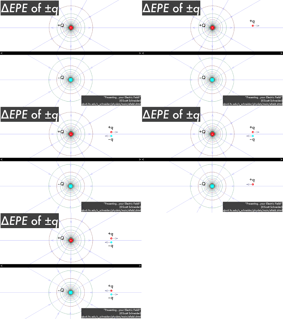
Here, from before, we show the electrical fields and potentials filling in all space surrounding a positive or a negative source charge. Putting a positive test charge in the presence of these electrical fields and potentials will cause an electrical force to be exerted along a field line, which would also point in the direction of decreasing potential and decreasing potential energy; while putting a negative test charge in the presence of these electrical fields and potentials will cause an electrical force to be exerted in the opposite direction of a field line, which would point in the direction of increasing potential, but decreasing potential energy.

In any case, as a check the direction of the force on any source charge q should be attractive or repulsive depending on whether it has the opposite or same sign as the source charge Q, and also check that the source charge q moves in the direction that would decrease its electric potential energy. However, positive test charges move in the direction of decreasing potential, while negative test charges move in the direction of increasing potential! (If all this sounds confusing, at least be assured that these rules are consistent.)

As previously above, we visualized a positive source charge +Q as a "peak." Here we have a positive test charge +q as a hapless snowmobiler on this "peak." Initially as the snowmobiler rides up the "peak," increasing his potential and increasing his potential energy, work is required to push it "uphill" (provided by an external source, here the snowmobile engine). Left alone, the snowmobile and snowmobiler will slide "downhill," in the direction of decreasing potential and decreasing potential energy (as we have seen before, for two positive charges separating from each other). What would happen if the snowmobiler were a negative test charge –q? Then we would observe the very odd behavior of this negative snowmobiler sliding "uphill," in the direction in increasing potential--but this would be the direction of decreasing potential energy, as we have seen before, for a negative charge and a positive charge getting closer to each other.

What would happen if there was a negative source charge –Q creating a "well?" Then a positive test charge +q snowmobiler, left alone, would slide "downhill," in the direction of decreasing potential and decreasing potential energy (as we have seen before, for a negative charge and positive charge getting closer to each other). Then consider the very odd case of a negative test charge –q snowmobiler sliding on this "well"--we would observe the very odd behavior of this negative snowmobiler sliding "uphill," in the direction in increasing potential--but this would be the direction of decreasing potential energy, as we have seen before, for two negative charges separating from each other. (Video source: "Grazy hill climb crash with go pro cam.")