20130207

Astronomy quiz archive: stars/sun/seasons/moon phases

Astronomy 210 Quiz 1, spring semester 2013
Cuesta College, San Luis Obispo, CA

Section 30674, version 1
Exam code: quiz01N1nk


Section 30674
0- 8.0 :
8.5-16.0 : ***** [low = 12.0]
16.5-24.0 : ********
24.5-32.0 : ************* [mean = 25.6 +/- 7.6]
32.5-40.0 : ***** [high = 40.0]


Section 30676, version 1
Exam code: quiz01Sp4t


Section 30676
0- 8.0 : * [low = 4.0]
8.5-16.0 : ****
16.5-24.0 : ************************* [mean = 21.9 +/- 6.2]
24.5-32.0 : **************
32.5-40.0 : * [high = 33.0]

20130204

Astronomy in-class activity: planet-hunting

Astronomy 210 In-class activity 6 v.13.02.01, spring semester 2013
Cuesta College, San Luis Obispo, CA

Students find their assigned groups of three to four students, and work cooperatively on an in-class activity worksheet to determine where in the sky each naked-eye planet will be observed on a given date (here, February 6, 2013).


Previous posts:

20130126

Presentation: interference

And he has a butler.
This is your neighbor. You know, the guy who plays his stereo system way too loud. (Video link: "Maxell Tape: Blown Away (1979).")
Butler: "The usual sir?"
Blown Away Guy: "Please."
(Tape player starts blaring Richard Wagner's Walkürenritt ("Ride of the Valkyries").)
Narrator: "Even after 500 plays, our high-fidelity tape still delivers...high fidelity."
Nobody who plays cassette tapes over a two-channel sound system deserves to crank up the volume.
Maybe we can do something about that, next time we just happen to be in his apartment (invited or not), with some minor adjustments to his stereo system wiring.

Last semester we discussed the behavior of sound waves, and so far this semester have been extending those concepts to model the behavior of electromagnetic radiation. Here we specifically look at the superposition of two waves in general, first sound, then later extending these concepts to visible light in a subsequent presentation.

First, defining a few terms.

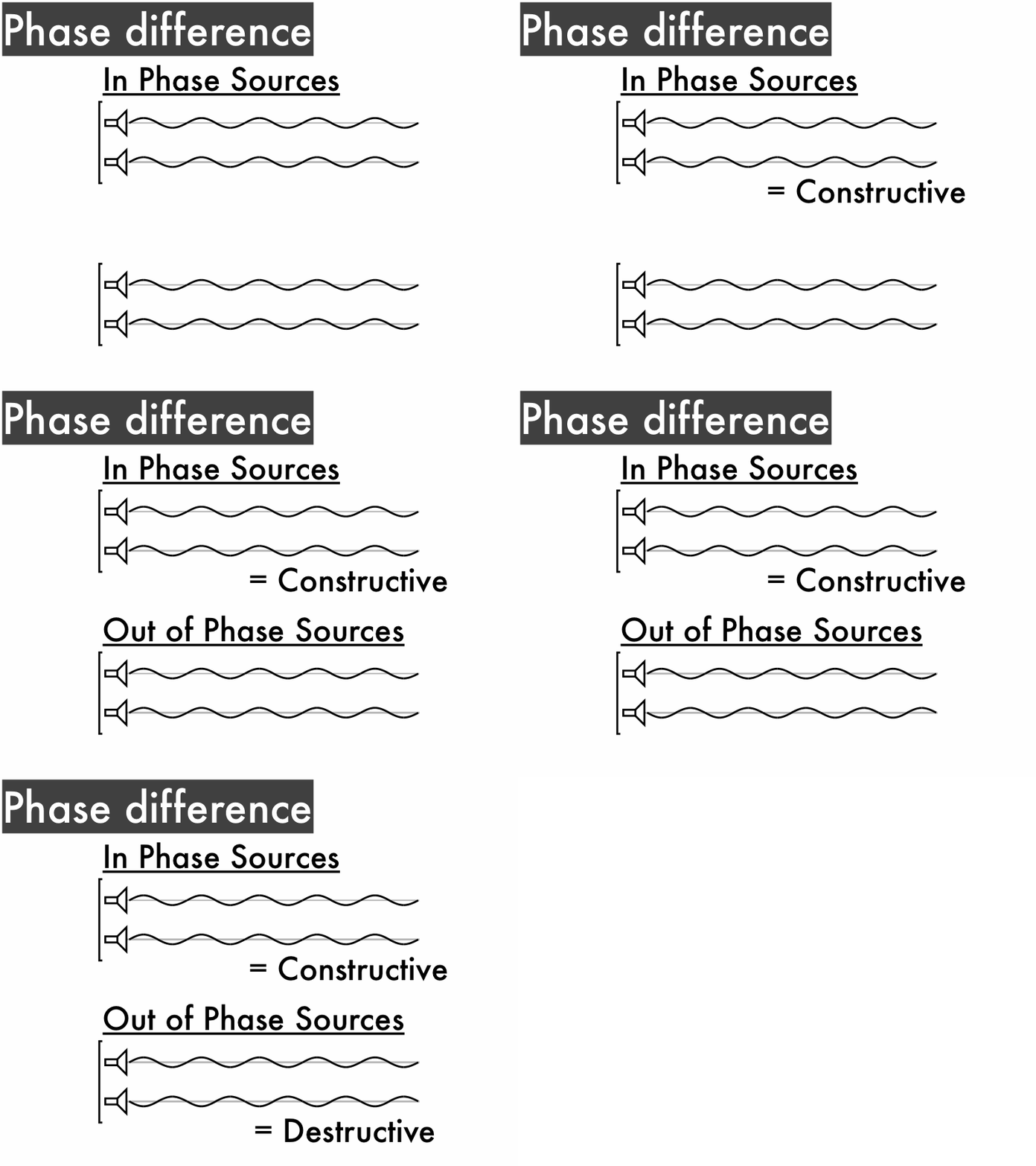
Here we have two speakers, which are our sources of two sound waves. Since they are plugged into the same frequency source, they will generate sound waves of the same frequency f (which is depends only on the source), same speed v (which depends only on the medium), and thus the same wavelength λ (which depends on both f and v). If the speakers are wired the same way--red and black wires to red and black plugs--then they will oscillate in phase, with both speaker cones moving forward and backwards in unison.

However, if the speakers are wired with opposite polarities--here, the speaker on the left is wired with black and red wires to red and black plugs--then they will oscillate out of phase, with one speaker cone moving backwards while the other is moving forwards, and then forwards while the other is moving backwards.

When we have two in phase sound sources with speaker cones that move in unison with each other, then the waves they generate will have crests and troughs that line up with each other. The superposition of these two waves will result in constructive interference, which will be a single louder wave.

If instead we have two out of phase sources with speaker cones that move contrary to each other, then the waves they generate will have crests and troughs that line up with the other speaker's troughs and crests. The superposition of these two waves will result in destructive interference--which would ideally be silence--but more realistically would be a single wave that is much quieter. (This is what would result if you switched the speaker wire polarities for one side of your neighbor's stereo system.)

Now let's consider two in phase sound speakers, but for an observer located at a position where the distance from each speaker--the path length--is different.

Here waves from the left speaker travel approximately 0.81 m, while the path length for the waves from the right speaker is about 0.63 m. The path differencel is the (absolute value) of how much farther one wave travels than the other, so in this case ∆l = 0.81 m - 0.63 m = 0.18 m.

This is why you should sit in the 'sweet spot,' equally distant from both speakers in order to minimize any path differences that may cause destructive interference.
Even with in phase speakers we can get either constructive or destructive interference, if the waves from each speaker travel different path lengths, resulting in certain path differences ∆l. For two in phase speakers where one wave travels a half-wavelength longer than the other, the path difference is (1/2)λ, and as a result crests and troughs line up with the other speaker's troughs and crests: destructive interference.

For two in phase speakers where one wave travels a whole wavelength longer than the other, the path difference is λ, and as a result crests and troughs line up with the other speaker's crests and troughs: constructive interference.

Second, mixing up the source phases and path difference conditions for constructive and destructive interference.

Here are two cases where both source phases and path differences matter. The top example is where two sources with a half-wavelength path difference results in constructive interference. The bottom example is where two sources with a whole wavelength path difference results in destructive interference. So how can we account for cases like these?

Whether constructive or destructive interference occurs depends on both the sources (how the waves start out, whether in phase or out of phase) and the path difference ∆l (how far each wave travels farther than the other, whether a whole wavelength or a half-wavelength longer than the other). There are four different cases:
  • For two in phase sources, if each wave travels a whole wavelength longer than the other, then constructive interference occurs (this is the solid black line.)
  • For two in phase sources, if each wave travels a half-wavelength longer than the other, then destructive interference occurs (this is the dashed black line.)
  • For two out of phase sources, if each wave travels a whole wavelength longer than the other, then destructive interference occurs (this is the solid red line.)
  • For two out of phase sources, if each wave travels a half-wavelength longer than the other, then constructive interference occurs (this is the dashed red line.)
Right now these different conditions look rather intimidating, so we'll make sure to be able to practice applying these conditions to various scenarios of in phase sources and out of phase sources with different shifted positions. Remember, there are only four unique cases of different phases and path differences.

20130123

Overheard: all the starwheel questions

2013-01-23_19-39-28_490
http://www.flickr.com/photos/waiferx/8409668035/
Originally uploaded by Waifer X

(Overheard after students practice all three possible types of starwheel (planisphere) questions in class.)

Instructor: "Hey, uh--do you know what Rage Comics are?" (Beat.) "But of course you do, you're college students." (Draws in Rage Comics' "All of the Things" character next to outline of possible starwheel questions.)

20130115

Presentation: optical instruments

Look at them. Just look at them. Old school optical instruments: microscopes and telescopes.


Make sure you get a chance to look through them in class--use the pocket microscopes to look at laptop and smartphone screens, and the telescopes to look at the posters across the room. (Focus the microscopes using the ridged wheels, and focus the telescopes by sliding the eyepiece tube in or out.)

First, the similarities between microscopes and telescopes.

A microscope consists of a (short) tube that holds two lenses apart from each other: an objective lens in the front, and the eyepiece in the back.

Similarly, telescope consists of a (long) tube that holds two lenses apart from each other: an objective lens in the front, and the eyepiece in the back.

Let's look at the two-lens model of a microscope, where the objective is lens 1, and the eyepiece is lens 2. The objective takes the light from object, and creates a real image 1 (how do you know that this would be a real image?). This real image 1 then becomes the object 2 for the eyepiece.

Now let's look at the two-lens model of a telescope, where the objective is lens 1, and the eyepiece is lens 2. The objective takes the light from object, and creates a real image 1 (how do you know that this would be a real image?). This real image 1 then becomes the object 2 for the eyepiece.

Second, differences between microscopes and telescopes. (You may have started to notice some of them already.)

For the microscope ray tracing, the object 1 is placed just outside of the focal point of the objective, which makes a greatly enlarged real image 1. (Which ray tracing(s) ((1)-(10)) best match(es) this?)

Then this image 1 becomes the object 2 for the eyepiece, where it is placed on the focal point of the eyepiece to maximize its angular magnification. (Which ray tracing(s) ((1)-(10)) best match(es) this?)

(Strangely enough, the "tube length" for microscopes is defined as the distance measured between the objective and eyepiece focal points. Compare this definition to the "barrel length" for telescopes, below.)

Then for the telescope ray tracing, the object 1 is extremely distant, such that its rays are essentially parallel. The objective lens then focuses these parallel light rays onto an image 1 located at its focal point. (Which ray tracing(s) ((1)-(10)) best match(es) this?)

Then this image 1 becomes the object 2 for the eyepiece, where it is placed on the focal point of the eyepiece to maximize its angular magnification. (Which ray tracing(s) ((1)-(10)) best match(es) this?)

Where are the ray tracings for microscopes and telescopes most similar? Where do they differ?

(Note how the "barrel length" for telescopes is defined as the distance measured between the objective to the eyepiece lenses, which is the same as the sum of their focal points. Compare this definition to the "tube length" for microscopes, above.)

For the microscope equation, 'L' is the distance between the objective and eyepiece lenses, and 'N' refers to the near point, which is assumed to be the nominal 25 cm value.
Notice the negative sign in the angular magnification equations for microscopes and telescopes--what does this mean for the orientation of the final image seen through the eyepiece? Did you notice this for both the microscope and telescope?

What type of focal lengths would you want for the objective lens of a microscope? Telescope? What type of focal lengths would you want for the eyepiece lens of a microscope? Telescope?

The telescope angular magnification equation does not explicitly refer to the distance between the objective lens and the eyepiece lens. How is this distance related to the focal lengths fo and fe of the objective and eyepiece?

20130114

Presentation: magnifiers

Look at this magnifying glass. Just look at it. Um, through it.

In this presentation we will look through, um, at how magnifiers magnify. (In the next presentation we'll see how these magnifying lenses are used as eyepieces in telescopes and microscopes.)

First, defining what magnifiers do, and to what.

The angular size Θ is not the actual size, it is a measure of how large an angle it subtends with your eye at the origin, and is a measure of how big something "seems" from your viewpoint.

The angular magnification M (upper-case M, to distinguish it from linear magnification lower-case m) is a numerical factor denoting how much larger the angular size of something appears as seen through a magnifier, compared to with just the unaided eye.

Why would anyone use a magnifier with an angular magnification of less than 1?
When a converging lens with a focal length f is used a magnifier, the angular magnification is the ratio of the angular size as seen through the magnifier, compared to the angular size as seen with an unaided eye. This is also the ratio of the near point (the nominal closest distance an unaided eye can focus on, 25 cm) to the the focal length of the magnifier.

Second, the process of magnification using a magnifier.

A magnifying lens doesn't magnify...it FOCUSIFIES!
Let's start with a rather provocative statement: a magnifying lens doesn't really magnify. Here we see a close-up (but unfocused) view of a pliers, and the same pliers at the same distance using a magnifying lens. The angular size of the pliers is relatively unchanged (after accounting for extreme defocusing circle of confusion blurring)!

Consider an Ames room, which is constructed that a person moving along the back of the room (which is actually greatly skewed) will be farther away or closer to an observer's eye, causing the person's angular size to change unexpectedly. This is the main idea behind angular magnification, which is merely caused by bringing an object closer to an eye.


Bringing something closer biggifies it. BIGGIFIES.
Bringing an object closer to an eye increases its angular size, but there is a practical limit to how close an object can be brought such that the eye still can focus on it--the near point, with the nominal value being 25 cm. Any closer would still increase the angular size of the object, but the eye would no longer be able to focus clearly on it.


Now compare these two views of the pliers, without and with a magnifying lens. Note that without the magnifying lens, the view is focused at ∞, where objects on the horizon are sharply in focus, and the pliers is out of focus. With the magnifying lens, the view is still focused at ∞, but now the pliers is in focus, meaning that the virtual image produced by the magnifying lens is at ∞. (How do you know that this is a virtual image? Which ray tracing best matches this?) This is because the pliers is on the focal point of the magnifying lens, which produces a virtual image (of the same angular size) out at infinity.

So to refine our understanding of what magnifiers actually do:
  • The maximum angular size of an object as seen by an unaided (nominal) eye is when the object is placed 25 cm away.
  • For a magnifying lens with a focal length f of less than 25 cm, the object can then be brought closer (up to the focal point of the magnifying lens), such that the magnifying lens allows the eye to be able to focus (at ∞) on an object held closer than 25 cm.
  • Closer is bigger.
One could also think of the magnifying glass as increasing the accommodation ability of the eye to focus on objects nearer than 25 cm, such that objects can be brought closer in order to increase their angular size.