Showing posts with label battery. Show all posts

20200422

Physics quiz question: ammeter reading after switch is closed

Physics 205B Quiz 5, spring semester 2018
Cuesta College, San Luis Obispo, CA

An ideal 6.0 V emf source is connected to two light bulbs, a resistor, and an ideal ammeter, and an open switch. When the switch is closed, the ammeter reading will:
(A) decrease.
(B) remain constant.
(C) increase.
(D) (Not enough information is given.)

Correct answer (highlight to unhide): (A)

When the switch is open, the 1.0 Ω light bulb will be dark as no current will pass through it.  The current in this circuit will start at the 6.0 V emf, pass through the ammeter, go through the 7.5 Ω resistor, and then through the 2.0 Ω resistor, and back to the 6.0 V emf.  

The equivalent resistance Req of this circuit is 7.5 Ω + 2.0 Ω = 9.5 Ω.  

The current I through this circuit is (6.0 V)/(9.5 Ω) = 0.63 A, which is the ammeter reading.

When the switch is closed, then the 1.0 Ω light bulb is in parallel with the 7.5 Ω resistor.

The equivalent resistance Req of this circuit is 2.0 Ω + ((1/1.0 Ω) + (1/7.5 Ω))–1 = 2.88 Ω.

The current Iemf through the emf is (6.0 V)/(2.88 Ω) = 2.08 A.

Now let's figure out how much current goes through the ammeter when the switch is closed, as the 2.08 A that passes through the 6.0 V emf will split with some either going through the switch path or going through the ammeter path, as given by Kirchhoff's junction rule:

Iemf = Iswitch + Iammeter.  

Let's apply Kirchhoff's loop rule for the clockwise emf-ammeter-7.5 Ω-2.0 Ω round trip path:

voltage rises = voltage drops,

6.0 V = ∆V7.5 Ω + ∆V2.0 Ω,

and then apply Ohm's law to the right-hand side terms:

6.0 V = Iammeter·(7.5 Ω) + Iemf·(2.0 Ω),

and since we already know Iemf= 2.08 A, then:

6.0 Ω = Iammeter·(7.5 Ω) + (2.08 A)·(2.0 Ω),

0.25 A = Iammeter,

which means the ammeter reading will decrease from its previous reading of 0.63 A when the switch was still open.

Sections 30882, 30883
Exam code: quiz05z0m6
(A) : 22 students
(B) : 8 students
(C) : 4 students
(D) : 0 students

Success level: 65%
Discrimination index (Aubrecht & Aubrecht, 1983): 0.70

20200331

Physics quiz question: power dissipated by resistor in parallel circuit

Physics 205B Quiz 5, spring semester 2018
Cuesta College, San Luis Obispo, CA

An ideal 6.0 V emf source is connected to a resistor and two light bulbs. The electrical power used by the 4.0 Ω resistor is:
(A) 1.5 W.
(B) 9.0 W.
(C) 24 W.
(D) 96 W.

Correct answer (highlight to unhide): (B)

The basic equation for the power dissipated by the 4.0 Ω resistor is:

Presistor = Iresistor·ΔVresistor,

where the current through the resistor Iresistor is not equal to the current passing through the 6.0 V emf source (Icircuit = ΔVresistor/Req), due to the junction rule. However, we do not need to find Iresistor, as we can appeal to Ohm's law:

Iresistor = ΔVresistor/Rresistor,

such that we can substitute this into the basic power equation, and result in a "specialized" form of the power equation for this resistor:

Presistor = Iresistor·ΔVresistor,

Presistor = (ΔVresistor/Rresistor)·ΔVresistor,

Presistor = (ΔVresistor)2/Rresistor.

To find the ΔVresistor voltage used by the resistor, we apply the loop rule in the clockwise direction, starting from lower right-hand corner, through the 6.0 V emf source, then through the 4.0 Ω resistor before returning to the starting point in the lower right-hand corner (the loop rule can be applied to any round-trip loop in a circuit, even if there are other parts of this circuit):

"voltage supplied = voltage used,"

Vrises = ∆Vdrops,

(6.0 V) = ΔVresistor.

Then we can evaluate the "specialized" form for the power used by the resistor:

Presistor = (ΔVresistor)2/Rresistor,

Presistor = (6.0 V)2/(4.0 Ω) = 9.0 W.

(This "specialized" equation for power should only be used if the voltage used by the circuit element is known already either from the loop rule (as was done here) or from Ohm's law.)

(Response (A) is the numerical value for the current flowing through the resistor; response (C) is ΔVresistor·Rresistor; response (D) is ΔVresistor)2·(Rresistor)2.)

Sections 30882, 30883
Exam code: quiz05z0m6
(A) : 5 students
(B) : 19 students
(C) : 9 students
(D) : 1 student

Success level: 56%
Discrimination index (Aubrecht & Aubrecht, 1983): 0.83

20190422

Physics quiz archive: circuits (2)

Physics 205B Quiz 5, spring semester 2019
Cuesta College, San Luis Obispo, CA
Sections 30882, 30883, version 1
Exam code: quiz05eXpL


Sections 30882, 30883 results
0- 6 :  
7-12 :   ** [low = 9]
13-18 :   ****************
19-24 :   ***************** [mean = 20.2 +/- 4.7]
25-30 :   **** [high = 30]

20190410

Physics quiz archive: capacitors, circuits

Physics 205B Quiz 4, spring semester 2019
Cuesta College, San Luis Obispo, CA
Sections 30882, 30883, version 1
Exam code: quiz04KhhF


Sections 30882, 30883 results
0- 6 :  
7-12 :   **** [low = 9]
13-18 :   *****
19-24 :   *************** [mean = 23.4 +/- 6.0]
25-30 :   ***************** [high = 30]

20180416

Physics quiz archive: circuits (2)

Physics 205B Quiz 5, spring semester 2018
Cuesta College, San Luis Obispo, CA
Sections 30882, 30883, version 1
Exam code: quiz05z0m6


Sections 30882, 30883 results
0- 6 :  
7-12 :   ***** [low = 9]
13-18 :   *************** [mean = 18.4 +/- 4.4]
19-24 :   ******************* [high = 24]
25-30 :  

20180328

Physics quiz archive: capacitors, circuits

Physics 205B Quiz 4, spring semester 2018
Cuesta College, San Luis Obispo, CA
Sections 30882, 30883, version 1
Exam code: quiz04Md1o


Sections 30882, 30883 results
0- 6 :  
7-12 :   *** [low = 9]
13-18 :   ************
19-24 :   ************ [mean = 20.3 +/- 5.3]
25-30 :   ***** [high = 27]

20170415

Physics quiz archive: circuits (2)

Physics 205B Quiz 5, spring semester 2017
Cuesta College, San Luis Obispo, CA
Sections 30882, 30883, version 1
Exam code: quiz05vLeY


Sections 30882, 30883 results
0- 6 :   *** [low = 3]
7-12 :   ****
13-18 :   ******* [mean = 17.7 +/- 7.0]
19-24 :   *********
25-30 :   *** [high = 27]

20170409

Physics quiz question: separating capacitor plates

Physics 205B Quiz 4, spring semester 2017
Cuesta College, San Luis Obispo, CA

A parallel plate capacitor is charged by connecting it to a 9.0 V battery, and is then disconnected. Afterwards, the parallel plates are separated a little more, without any charge on the plates being lost. As the parallel plates are separating, the potential difference of the capacitor:
(A) decreases.
(B) remains constant.
(C) increases.
(D) (Not enough information is given.)

Correct answer (highlight to unhide): (C)

Separating the parallel plates of the capacitor will decrease the capacitance, as increasing d will decrease C in:

C = A/(4·π·k·d).

Since the battery is disconnected from the capacitor, the charge Q on the capacitor will remain constant, as the plates are electrically isolated as they are separated from each other, resulting in an increase in ∆V (while decreasing C), as seen from:

C = Q/∆V.

Student responses
Sections 30882, 30883
Exam code: quiz04Br7w
(A) : 7 students
(B) : 7 students
(C) : 9 students
(D) : 0 students

Success level: 39%
Discrimination index (Aubrecht & Aubrecht, 1983): 0.46

20170331

Physics quiz archive: capacitors, circuits

Physics 205B Quiz 4, spring semester 2017
Cuesta College, San Luis Obispo, CA
Sections 30882, 30883, version 1
Exam code: quiz04Br7w


Sections 30882, 30883 results
0- 6 :  
7-12 :   ******* [low = 9]
13-18 :   ******** [mean = 17.1 +/- 5.4]
19-24 :   ******
25-30 :   ** [high = 30]

20170320

Physics quiz question: voltmeter reading along "top" of series circuit

Physics 205B Quiz 5, spring semester 2015
Cuesta College, San Luis Obispo, CA

An ideal 4.5 V emf source is connected to an ideal voltmeter, a light bulb, and two resistors, as shown at right. The voltmeter reading is:
(A) 0.26 V.
(B) 0.39 V.
(C) 2.1 V.
(D) 2.4 V.

Correct answer (highlight to unhide): (D)

Since the ideal voltmeter has an infinite resistance, no current flows through it, and only along the lower loop of the circuit (through the ideal emf source, the top left resistor, the light bulb, and then through the lower right resistor). Since the resistors and light bulb are wired in series, the equivalent resistance of the circuit is just the arithmetic sum of their individual resistances:

Req = 8.0 Ω + 1.5 Ω + 8.0 Ω = 17.5 Ω.

From Ohm's law, the current flowing through this simplified (one ideal emf and one equivalent resistor) is:

I = ε/Req = (4.5 V)/(17.5 Ω) = 0.2571428571 A.

Starting from the contact on the left, the difference in voltage detected by the voltmeter is the drop due to the top left resistor plus the drop due to the light bulb:

V = (–I·Rresistor) + (–I·Rlight bulb),

V = –I·(Rresistor + Rlight bulb),

V = –(0.2571428571 A)·(8.0 Ω + 1.5 Ω) = –2.4428571429 V,

or to two significant figures, the voltmeter reading is 2.4 V.

(Response (A) is the current I = ε/Req flowing through the circuit; response (B) is the voltage drop ∆V = I·Rlight bulb of just the 1.5 Ω light bulb; response (C) is the voltage drop ∆V = I·Rresistor of just the 8.0 Ω resistor.)

Sections 30882, 30883
Exam code: quiz05aL7y
(A) : 16 students
(B) : 6 students
(C) : 9 students
(D) : 16 students

Success level: 34%
Discrimination index (Aubrecht & Aubrecht, 1983): 0.62

Physics quiz question: ammeter readings in circuit perimeter

Physics 205B Quiz 5, spring semester 2015
Cuesta College, San Luis Obispo, CA

Two ideal ammeters are connected to circuit with a switch, an ideal 1.5 V emf source, a light bulb and a resistor, as shown at right. While the switch remains open, the __________ ammeter has a higher reading.
(A) top.
(B) bottom.
(C) (There is a tie, where both ammeters have a zero reading.)
(D) (There is a tie, where both ammeters have a finite, non-zero reading.)
(E) (Not enough information is given.)

Correct answer (highlight to unhide): (C)

While the switch remains open, the emf is isolated from the circuit, which is completed around its perimeter with just a light bulb, resistor, and two ammeters without any source of emf. Thus no current will flow through outer perimeter of this circuit, such that both ammeters will read zero.

Sections 30882, 30883
Exam code: quiz05aL7y
(A) : 2 students
(B) : 3 students
(C) : 37 students
(D) : 5 students
(E) : 0 students

Success level: 79%
Discrimination index (Aubrecht & Aubrecht, 1983): 0.32

20160614

Physics quiz question: ammeter reading, connected in series with voltmeter

Physics 205B Quiz 5, spring semester 2016
Cuesta College, San Luis Obispo, CA

An ideal 3.2 V emf source is connected to an ideal voltmeter and ammeter, a light bulb, and a resistor. The light bulb is lit. The ammeter reading is:
(A) zero.
(B) some finite, non-zero value below 0.67 A.
(C) exactly 0.67 A.
(D) some finite value above 0.67 A.
(E) ∞.

Correct answer (highlight to unhide): (A)

An ideal ammeter has zero resistance, but it is connected in series to an ideal voltmeter, which has an infinite resistance. Thus no current will flow through the upper loop of this circuit, such that the ammeter will read zero.

(Response (C) is the amount of current flowing through the emf, light bulb, and resistor in the lower loop of this circuit.)
Sections 30882, 30883
Exam code: quiz05Tt1p
(A) : 17 students
(B) : 5 students
(C) : 11 students
(D) : 4 students
(E) : 1 student

Success level: 45%
Discrimination index (Aubrecht & Aubrecht, 1983): 0.26

Physics quiz question: power dissipated by light bulb in series circuit

Physics 205B Quiz 5, spring semester 2016
Cuesta College, San Luis Obispo, CA

An ideal 6.0 V emf source is connected to two light bulbs (each with a 1.2 Ω resistance), and a 0.50 Ω resistor. The electrical power used by the top light bulb is:
(A) 2.1 W.
(B) 5.1 W.
(C) 12 W.
(D) 30 W.

Correct answer (highlight to unhide): (B)

The equivalent resistance of this series circuit is the arithmetic sum of their resistances:

Req = 1.2 Ω + 1.2 Ω + 0.50 Ω = 2.9 Ω.

From Kirchhoff's junction rule, the amount of current flowing through the emf source and all three resistive circuit elements must be the same, as they are in series with each other, and the current flowing this circuit is given by applying Ohm's law to the entire equivalent circuit:

Ieq = ε/Req = (6.0 V)/(2.9 Ω).

Since we now know the resistance value of the top light bulb, and the amount of current flowing through it, the power dissipated by the top light bulb is then:

Ptop light bulb = Ieq·ΔVtop light bulb = Ieq·(Ieq·Rtop light bulb) = Ieq2·Rtop light bulb,

Ptop light bulb = ((6.0 V)/(2.9 Ω))2·(1.2 Ω) = 5.1367419737 W,

or to two significant figures, 5.1 W.

(Response (A) is the numerical value for the current flowing through the circuit Ieq = ε/Req = (6.0 V)/(2.9 Ω); response (C) is ((6.0 V)/(2.9 Ω))2·(2.9 Ω), which is the amount of power supplied by the emf source to rest of the circuit; response (D) is (6.0 V)2/(1.2 Ω), which would be the power dissipated by the top light bulb if it were to use up all of the voltage supplied by the emf (which would violate Kirchhoff's loop rule!).)

Sections 30882, 30883
Exam code: quiz05Tt1p
(A) : 4 students
(B) : 16 students
(C) : 13 students
(D) : 5 students

Success level: 43%
Discrimination index (Aubrecht & Aubrecht, 1983): 0.79

20160417

Physics quiz archive: circuits (2)

Physics 205B Quiz 5, spring semester 2016
Cuesta College, San Luis Obispo, CA
Sections 30882, 30883, version 1
Exam code: quiz05Tt1p


Sections 30882, 30883 results
0- 6 :  
7-12 :   *** [low = 12]
13-18 :   **************
19-24 :   ************* [mean = 20.8 +/- 5.0]
25-30 :   ******** [high = 30]

20160313

Physics quiz question: switching emf polarity

Physics 205B Quiz 4, spring semester 2015
Cuesta College, San Luis Obispo, CA

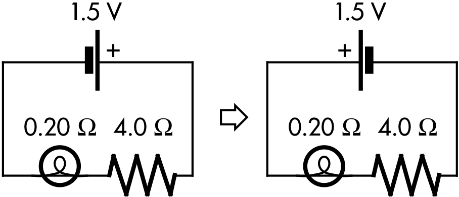
An ideal emf source is connected to a light bulb and a resistor, as shown at right. If the direction of the emf source is switched, the light bulb would then have __________ current passing through it.
(A) less.
(B) the same amount of.
(C) more.
(D) (Not enough information is given.)

Correct answer (highlight to unhide): (B)

The equivalent resistance of this circuit (resistor and light bulb are in series with the emf) is the sum of these resistances. Thus the current flowing through all parts of this series circuit is given by:

I = ∆V/Req = (1.5 V)/(4.0 Ω + 0.20 Ω) = (1.5 V)/(4.2 Ω) = 0.3571428571 A,

or to two significant figures, 0.36 A. This is regardless of whether the ± polarity of the emf is switched, which would change the direction of current leaving the + terminal of the emf to go through the light bulb first instead of the resistor first--it would still be the same 0.36 A of current flowing through all parts of each of these two circuits. (This is an application of Kirchhoff's junction rule, in the case here where there is no junction in either these series circuit.)

Sections 30882, 30883
Exam code: quiz04sm7H
(A) : 4 students
(B) : 30 students
(C) : 10 students
(D) : 0 students

Success level: 68%
Discrimination index (Aubrecht & Aubrecht, 1983): 0.85

Physics quiz question: light bulb "between" two emfs

Physics 205B Quiz 4, spring semester 2015
Cuesta College, San Luis Obispo, CA

Two ideal emf sources are connected to a light bulb, as shown at right. The current flowing through the 6.0 V emf source is:
(A) 3.0 A.
(B) 11 A.
(C) 12 A.
(D) 21 A.

Correct answer (highlight to unhide): (D)

The equivalent emf of this circuit (the 6.0 V emf source and the 4.5 V emf source are in series with the light bulb, both ± polarities "stacked") is the sum of these emfs. Thus the current flowing through all parts of this series circuit is given by:

I = ∆Veq/R = (6.0 V + 4.5 V)/(0.50 Ω) = (10.5 V)/(0.50 Ω) = 21 A.

(This is an application of Kirchhoff's junction rule, in the case here where there is no junction in either these series circuit.)

(Response (A) is using the equivalent emf of the difference between the two emfs (the case where they would be connected in series with opposite ± polarities); response (B) is the sum of the two emf values (with the wrong units of amperes, to two significant figures), which could also erroneously be the sum of the two emf values together with the light bulb resistance value (again with the wrong units of amperes).)

Sections 30882, 30883
Exam code: quiz04sm7H
(A) : 4 students
(B) : 0 students
(C) : 9 students
(D) : 31 students

Success level: 70%
Discrimination index (Aubrecht & Aubrecht, 1983): 0.62

20150418

Physics quiz archive: circuits (2)

Physics 205B Quiz 5, spring semester 2015
Cuesta College, San Luis Obispo, CA
Sections 30882, 30883, version 1
Exam code: quiz05aL7y


Sections 30882, 30883 results
0- 6 :   * [low = 6]
7-12 :   ****
13-18 :   **********************
19-24 :   ************* [mean = 19.0 +/- 5.5]
25-30 :   ******* [high = 30]

20150403

Physics quiz archive: capacitors, circuits

Physics 205B Quiz 4, spring semester 2015
Cuesta College, San Luis Obispo, CA
Sections 30882, 30883, version 1
Exam code: quiz04sm7H


Sections 30882, 30883 results
0- 6 :   ****** [low = 0]
7-12 :   *********
13-18 :   **************** [mean = 15.4 +/- 7.0]
19-24 :   ***********
25-30 :   ** [high = 30]

20140410

Physics quiz archive: circuits (2)

Physics 205B Quiz 5, spring semester 2014
Cuesta College, San Luis Obispo, CA
Sections 30882, 30883, version 1
Exam code: quiz05b4L8


Sections 30882, 30883 results
0- 6 :   **** [low = 3]
7-12 :   **********
13-18 :   ********* [mean = 17.0 +/- 6.7]
19-24 :   ***********
25-30 :   **** [high = 30]

20140405

Physics quiz question: "backwards" emf

Physics 205B Quiz 4, spring semester 2014
Cuesta College, San Luis Obispo, CA

Cf. Giambattista/Richardson/Richardson, Physics, 2/e, Problem 18.37

Three ideal emf sources are connected to a resistor, as shown at right. The current flowing through the resistor is:
(A) 1.6 A.
(B) 1.8 A.
(C) 2.0 A.
(D) 9.3 A.

Correct answer (highlight to unhide): (A)

The equivalent emf of this circuit is the sum of these emfs, however the polarity of the 1.2 V emf source is "backwards" with respect to the 9.0 V and the 1.5 V emf sources. Thus the equivalent emf is given by:

Veq = –1.2 V + 9.0 V + 1.5 V = 9.3 V.

Thus the current flowing through all parts of this series circuit is given by:

I = ∆Veq/R = (9.3 V)/(6.0 Ω) = 1.55 A,

which to two significant figures is 1.6 A.

(Response (B) is (+9.0 V + 1.5 V)/(6.0 Ω); response (C) is (1.2 V +9.0 V + 1.5 V)/(6.0 Ω); response (D) is (–1.2 V +9.0 V + 1.5 V).)

Sections 30882, 30883
Exam code: quiz04mCnC
(A) : 11 students
(B) : 4 students
(C) : 18 students
(D) : 3 students

Success level: 31%
Discrimination index (Aubrecht & Aubrecht, 1983): 0.28