Showing posts with label circuits. Show all posts

20190510

Physics midterm problem: brightness of light bulbs in circuit

Physics 205B Midterm 2, spring semester 2019
Cuesta College, San Luis Obispo, CA

An ideal 9.0 V emf source is connected to several light bulbs that all have the same resistance. Calculate the powers dissipated (in watts) for each of these light bulbs. Show your work and explain your reasoning using Kirchhoff's rules, Ohm's law, and properties of electrical power.

Solution and grading rubric:
  • p:
    Correct. Solves for the powers dissipated by each light bulb by:
    1. finding equivalent resistance of the circuit by recognizing that the top light bulb is in series to the lower three parallel light bulbs);
    2. applying Ohm's law to determine the current of the equivalent circuit, which is the current flowing through the top light bulb;
    3. determines the power dissipated by the top light bulb;
    4. applies Kirchhoff's loop and/or junction rules to solve for the voltage difference used by and/or the current flowing through each of the lower three parallel light bulbs; and
    5. determines the power dissipated by each of the lower three parallel light bulbs.
  • r:
    Nearly correct, but includes minor math errors. Typically incorrect calculation in (1) or in (5), but otherwise everything else is consistent with this error.
  • t:
    Nearly correct, but approach has conceptual errors, and/or major/compounded math errors. Multiple issues in (1)-(5), but still attempts to systematically analyze most of (1)-(5) even with wrong numerical values.
  • v:
    Implementation of right ideas, but in an inconsistent, incomplete, or unorganized manner. Some attempt at applying Kirchhoff's rules, Ohm's law, and properties of electrical power.
  • x:
    Implementation of ideas, but credit given for effort rather than merit. No clear attempt at applying Kirchhoff's rules, Ohm's law, and properties of electrical power.
  • y:
    Irrelevant discussion/effectively blank.
  • z:
    Blank.
Grading distribution:
Sections 30882, 30883
Exam code: midterm02u7aH
p: 10 students
r: 6 students
t: 7 students
v: 18 students
x: 2 students
y: 0 students
z: 0 students

A sample "p" response (from student 1982):

Another sample "p" response (from student 8812):

20190422

Physics quiz archive: circuits (2)

Physics 205B Quiz 5, spring semester 2019
Cuesta College, San Luis Obispo, CA
Sections 30882, 30883, version 1
Exam code: quiz05eXpL


Sections 30882, 30883 results
0- 6 :  
7-12 :   ** [low = 9]
13-18 :   ****************
19-24 :   ***************** [mean = 20.2 +/- 4.7]
25-30 :   **** [high = 30]

20190410

Physics quiz archive: capacitors, circuits

Physics 205B Quiz 4, spring semester 2019
Cuesta College, San Luis Obispo, CA
Sections 30882, 30883, version 1
Exam code: quiz04KhhF


Sections 30882, 30883 results
0- 6 :  
7-12 :   **** [low = 9]
13-18 :   *****
19-24 :   *************** [mean = 23.4 +/- 6.0]
25-30 :   ***************** [high = 30]

20180416

Physics quiz archive: circuits (2)

Physics 205B Quiz 5, spring semester 2018
Cuesta College, San Luis Obispo, CA
Sections 30882, 30883, version 1
Exam code: quiz05z0m6


Sections 30882, 30883 results
0- 6 :  
7-12 :   ***** [low = 9]
13-18 :   *************** [mean = 18.4 +/- 4.4]
19-24 :   ******************* [high = 24]
25-30 :  

20180328

Physics quiz archive: capacitors, circuits

Physics 205B Quiz 4, spring semester 2018
Cuesta College, San Luis Obispo, CA
Sections 30882, 30883, version 1
Exam code: quiz04Md1o


Sections 30882, 30883 results
0- 6 :  
7-12 :   *** [low = 9]
13-18 :   ************
19-24 :   ************ [mean = 20.3 +/- 5.3]
25-30 :   ***** [high = 27]

20170507

Physics midterm problem: pencil lead variable resistor

Physics 205B Midterm 2, spring semester 2017
Cuesta College, San Luis Obispo, CA

A real battery with an emf of 6.0 V and an internal resistance of r = 1.2 Ω is attached to an ideal voltmeter, and is connected to an ideal ammeter and a pencil lead that acts as a variable resistor. If the amount of pencil lead between the contacts is shortened such that its resistance is reduced from 8.0 Ω to 1.0 Ω, discuss why the voltmeter reading will decrease while the ammeter reading will increase. Show your work and explain your reasoning using Kirchhoff's rules, Ohm's law, and properties of ammeters and voltmeters.

Solution and grading rubric:
  • p:
    Correct. Explains why the voltmeter reading will decrease while the ammeter reading will increase as the amount of pencil lead between the contacts is shortened by discussing:
    1. the decrease in the resistance of the pencil lead resistor will reduce the equivalent resistance of the circuit (pencil lead and internal resistance are in series), such that from applying Ohm's law the amount of current passing everywhere through the circuit will increase, resulting in a higher ammeter reading; and
    2. the voltmeter measures the potential difference of the 6.0 V rise from the emf and the voltage drop Ir from the internal resistance, such that an increase in current will result in a lower voltage reading ΔV = +ε − Ir.
  • (May instead discuss how the voltmeter is equivalently measuring the voltage drop ΔV = −IR across the pencil lead resistor, but must clearly show that the eight-fold decrease in the resistance (from 8.0 Ω to 1.0 Ω) will be larger than the corresponding approximate four-fold increase in current (0.65 A to 2.7 A) to result in a lower voltage reading.)
  • r:
    Nearly correct, but includes minor math errors.
  • t:
    Nearly correct, but approach has conceptual errors, and/or major/compounded math errors. At least numerically or qualitatively demonstrates how current would increase, but does not definitely show why voltmeter reading would decrease.
  • v:
    Implementation of right ideas, but in an inconsistent, incomplete, or unorganized manner. Some attempt at applying Kirchhoff's rules, Ohm's law, and equivalent resistance.
  • x:
    Implementation of ideas, but credit given for effort rather than merit. Approach other than that of applying Kirchhoff's rules, Ohm's law, and properties of ammeters and voltmeters.
  • y:
    Irrelevant discussion/effectively blank.
  • z:
    Blank.
Grading distribution:
Sections 30882, 30883
Exam code: midterm02GruT
p: 12 students
r: 0 students
t: 8 students
v: 8 students
x: 1 student
y: 0 students
z: 0 students

A sample "p" response (from student 1412):

Another sample "p" response (from student 2643):

A sample "x" response (from student 9319):

20170415

Physics quiz archive: circuits (2)

Physics 205B Quiz 5, spring semester 2017
Cuesta College, San Luis Obispo, CA
Sections 30882, 30883, version 1
Exam code: quiz05vLeY


Sections 30882, 30883 results
0- 6 :   *** [low = 3]
7-12 :   ****
13-18 :   ******* [mean = 17.7 +/- 7.0]
19-24 :   *********
25-30 :   *** [high = 27]

20170331

Physics quiz archive: capacitors, circuits

Physics 205B Quiz 4, spring semester 2017
Cuesta College, San Luis Obispo, CA
Sections 30882, 30883, version 1
Exam code: quiz04Br7w


Sections 30882, 30883 results
0- 6 :  
7-12 :   ******* [low = 9]
13-18 :   ******** [mean = 17.1 +/- 5.4]
19-24 :   ******
25-30 :   ** [high = 30]

20160508

Physics midterm problem: change in voltmeter reading

Physics 205B Midterm 2, spring semester 2016
Cuesta College, San Luis Obispo, CA

A "AA" alkaline battery with an emf of 1.5 V and an internal resistance of r = 0.90 Ω is attached to an ideal voltmeter, with a R = 2.0 Ω light bulb that is wired in parallel with an open switch. Discuss why the voltmeter will have a lower reading after the switch is closed. Show your work and explain your reasoning using Kirchhoff's rules, Ohm's law, and properties of voltmeters.

Solution and grading rubric:
  • p:
    Correct. Recognizes that when the switch is open, the voltmeter will have a non-zero reading, and have a lower (zero) reading when the switch is closed, using one of two similar arguments:
    1. when the switch is open, there is a non-zero ΔV = +1.5 V − Ir reading, and when the switch is closed, from Kirchhoff's loop rule the voltage rise of +1.5 V from the emf must now exactly equal the −Ir voltage drop of the internal resistance of the battery, such that the voltmeter reading is now zero; or
    2. when the switch is open, there is a non-zero ΔV = − IR reading, and when the switch is closed, since the light bulb R is bypassed by a zero resistance switch, making ΔV = 0.
  • r:
    Nearly correct, but includes minor math errors. Does not sufficiently show numerically or qualitatively how voltmeter reading when switch is open is higher versus when the switch is closed.
  • t:
    Nearly correct, but approach has conceptual errors, and/or major/compounded math errors. At least has a conceptual understanding of how a voltmeter measures a potential difference, and how the switch changes the current flow when it is open versus when it is closed.
  • v:
    Implementation of right ideas, but in an inconsistent, incomplete, or unorganized manner. Some attempt at applying Kirchhoff's rules, Ohm's law, and equivalent resistance.
  • x:
    Implementation of ideas, but credit given for effort rather than merit. Approach other than that of applying Kirchhoff's rules, Ohm's law, and properties of voltmeters.
  • y:
    Irrelevant discussion/effectively blank.
  • z:
    Blank.
Grading distribution:
Sections 30882, 30883
Exam code: midterm02Mc4s
p: 7 students
r: 17 students
t: 4 students
v: 12 students
x: 2 students
y: 0 students
z: 0 students

A sample "p" response (from student 3158):

Another sample "p" response (from student 5433):

20160417

Physics quiz archive: circuits (2)

Physics 205B Quiz 5, spring semester 2016
Cuesta College, San Luis Obispo, CA
Sections 30882, 30883, version 1
Exam code: quiz05Tt1p


Sections 30882, 30883 results
0- 6 :  
7-12 :   *** [low = 12]
13-18 :   **************
19-24 :   ************* [mean = 20.8 +/- 5.0]
25-30 :   ******** [high = 30]

20150512

Physics midterm problem: comparing voltmeter readings

Physics 205B Midterm 2, spring semester 2015
Cuesta College, San Luis Obispo, CA

Cf. Giambattista/Richardson/Richardson, Physics, 2/e, Problem 18.72

Two voltmeters are connected to circuit with a switch, a light bulb, a resistor, and an emf source. All of these components are ideal. The resistance R of the resistor is greater than the resistance r of the light bulb. The top and bottom voltmeters have the same reading while the switch is open. Discuss why the top and bottom voltmeters will have different readings after the switch has been closed. Show your work and explain your reasoning using Kirchhoff's rules, Ohm's law, and properties of voltmeters.

Solution and grading rubric:
  • p:
    Correct. Understands that closing the switch would allow current to flow through the emf, resistor and light bulb series circuit, while completely by-passing the lower voltmeter, such that:
    1. the upper voltmeter would read a non-zero voltage difference of ΔV = +ε – IR (or equivalently, ΔV = (–)Ir); and
    2. the lower voltmeter would read zero, as there is no voltage drop due to the ideally zero resistance switch.
  • r:
    Nearly correct, but includes minor math errors. Understands that current will now flow through the circuit, but does not give correct reading of one of the voltmeters, but has correct reading for the other.
  • t:
    Nearly correct, but approach has conceptual errors, and/or major/compounded math errors. Understands that current will now flow through the circuit, but does not give correct readings for both voltmeters.
  • v:
    Implementation of right ideas, but in an inconsistent, incomplete, or unorganized manner. At least understands that current will now flow through the circuit.
  • x:
    Implementation of ideas, but credit given for effort rather than merit. Approach other than that of applying Kirchhoff's rules, Ohm's law, and properties of voltmeters.
  • y:
    Irrelevant discussion/effectively blank.
  • z:
    Blank.
Grading distribution:
Sections 30882, 30883
Exam code: midterm02m3tR
p: 8 students
r: 15 students
t: 7 students
v: 14 students
x: 3 students
y: 0 students
z: 0 students

A sample "p" response (from student 9178):

20150418

Physics quiz archive: circuits (2)

Physics 205B Quiz 5, spring semester 2015
Cuesta College, San Luis Obispo, CA
Sections 30882, 30883, version 1
Exam code: quiz05aL7y


Sections 30882, 30883 results
0- 6 :   * [low = 6]
7-12 :   ****
13-18 :   **********************
19-24 :   ************* [mean = 19.0 +/- 5.5]
25-30 :   ******* [high = 30]

20150403

Physics quiz archive: capacitors, circuits

Physics 205B Quiz 4, spring semester 2015
Cuesta College, San Luis Obispo, CA
Sections 30882, 30883, version 1
Exam code: quiz04sm7H


Sections 30882, 30883 results
0- 6 :   ****** [low = 0]
7-12 :   *********
13-18 :   **************** [mean = 15.4 +/- 7.0]
19-24 :   ***********
25-30 :   ** [high = 30]

20140511

Physics midterm problem: placing meters between batteries

Physics 205B Midterm 2, spring semester 2014
Cuesta College, San Luis Obispo, CA

Cf. Giambattista/Richardson/Richardson, Physics, 2/e, Problems 18.31, 18.72, 18.73

Two nickel-metal hydride (NiMH) batteries[*] each with an emf of 1.2 volts and an internal resistance of 0.1 Ω are connected to a 16.0 Ω light bulb[**], with an open gap between the batteries. In this gap, either an ideal voltmeter, or an ideal ammeter is to be connected. Determine (a) the voltmeter reading when it is connected between the batteries, and (b) the ammeter reading when it is connected between the batteries. Show your work and explain your reasoning using the properties of currents and potential differences, and Kirchhoff's rules and Ohm's law.

[*] "Cell charged: 100 milliohms," ti.com/lit/an/slva194/slva194.pdf.
[**] goo.gl/jLtakj.

Solution and grading rubric:
  • p:
    Correct. Applies Kirchhoff's loop rule and the fact that no current would flow through circuit (a) due to the infinite resistance of the ideal voltmeter to determine that should read 2.4 V; applies equivalent resistance and Ohm's law to determine the current flowing through the ideal (zero resistance) ammeter in circuit (b) should be 0.15 A.
  • r:
    Nearly correct, but includes minor math errors.
  • t:
    Nearly correct, but approach has conceptual errors, and/or major/compounded math errors. Voltmeter reading in circuit (a) is zero ("no current flow" = no voltage differences), infinite ("no current flow" = infinite/undefined voltage differences), or some value slightly less than 2.4 V due to internal resistance voltage drops (which would only be true if current were flowing through them), but still has the correct ammeter reading for circuit (b).
  • v:
    Implementation of right ideas, but in an inconsistent, incomplete, or unorganized manner. Some attempt at using Kirchhoff's rules, Ohm's law, and equivalent resistance.
  • x:
    Implementation of ideas, but credit given for effort rather than merit.
  • y:
    Irrelevant discussion/effectively blank.
  • z:
    Blank.
Grading distribution:
Sections 30882, 30883
Exam code: midterm02iF47
p: 3 students
r: 2 students
t: 23 students
v: 10 students
x: 2 students
y: 0 students
z: 0 students

A sample "p" response (from student 7979):

20140410

Physics quiz archive: circuits (2)

Physics 205B Quiz 5, spring semester 2014
Cuesta College, San Luis Obispo, CA
Sections 30882, 30883, version 1
Exam code: quiz05b4L8


Sections 30882, 30883 results
0- 6 :   **** [low = 3]
7-12 :   **********
13-18 :   ********* [mean = 17.0 +/- 6.7]
19-24 :   ***********
25-30 :   **** [high = 30]

20140405

Physics quiz archive: capacitors, circuits

Physics 205B Quiz 4, spring semester 2014
Cuesta College, San Luis Obispo, CA
Sections 30882, 30883, version 1
Exam code: quiz04mCnC


Sections 30882, 30883 results
0- 6 :
7-12 : ** [low = 12]
13-18 : *********
19-24 : *************** [mean = 21.8 +/- 4.8]
25-30 : ********** [high = 30]

20130419

Physics quiz archive: circuits (2)

Physics 205B Quiz 5, spring semester 2013
Cuesta College, San Luis Obispo, CA
Section 30882, version 1
Exam code: quiz05c4Rb


Section 30882 results
0- 6 : * [low = 6]
7-12 : ***********
13-18 : ********** [mean = 15.8 +/- 5.5]
19-24 : *********
25-30 : * [high = 27]

20130414

Physics quiz archive: capacitors, circuits

Physics 205B Quiz 4, spring semester 2013
Cuesta College, San Luis Obispo, CA
Section 30882, version 1
Exam code: quiz04eQu7


Section 30882 results
0- 6 : ** [low = 6]
7-12 : ********
13-18 : *************** [mean = 15.7 +/- 5.2]
19-24 : *******
25-30 : * [high = 27]

20130405

Presentation: generators

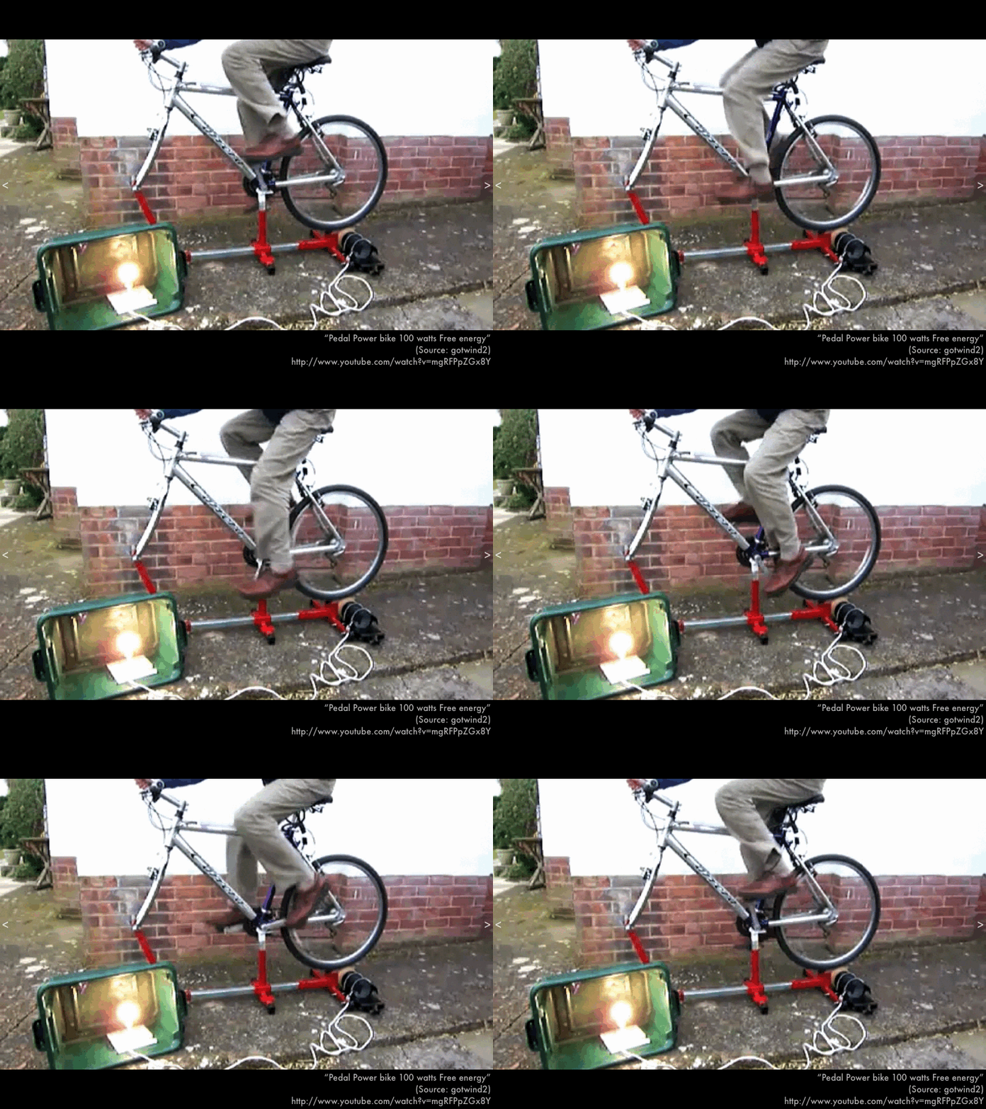
Look at this bicycle-powered generator. Just look at it. When the zombiepocalypse comes and civilization as we know it ends, would you be able to construct a generator from scratch?

In this presentation we will explain how generators work using right-hand rules of how magnetic fields exert forces on wires and loops. Later in a subsequent presentation we will explain how generators work using a magnetic flux approach.

First, "single-pass" generators, which can only be used once before having to be reset.

Consider a uniform magnetic B field, with uniform magnitude and direction (pointing into the plane of this page). A metal rod of length L is made to move at a constant speed and direction (to the right, in the plane of this page). As a result, the electrons in this metal rod will experience a force down along the rod (from either using the first right-hand rule to find the direction of the magnetic force on a (fictitious) positive charge, and reversing the direction of this force; or using the "left-hand rule"). As long as the rod is made to move through the magnetic field, the bottom end of the rod becomes negatively charged, while the top end of the rod becomes positively charged. The resulting difference in potential is a motional emf, and is the product of the rod's speed v and length L, and the magnitude B of the magnetic field. Thus moving a rod through a magnetic field makes the rod a battery!

Perhaps the ultimate proof of this principle was the Tethered Satellite System mission carried aboard the Space Shuttle, in which a 9.8 km wire was payed out as the Space Shuttle was moving through Earth's magnetic field. Actually much less wire was payed out before the tether broke, but there was a measured potential difference between each end of the tether.

Let's consider figurative depictions of "single-use" generators (more detailed consideration of how right-hand rules explain how these generators work will be covered in lecture). A rail generator has a rod made to move through a magnetic field, while the ends of the rod rest on rails, in order to make a complete circuit to take advantage of the motional emf generated in the moving rod (if the snowboard in this photo represents the rod, it would need to lie across both rails instead of sliding along one rail). In this sense this is a single-use generator, as you cannot indefinitely continue to slide the rod along the rail to generate a constant motional emf and current unless the rails are infinitely long in a magnetic field that is infinite in extent. Practically speaking, at some point you would need to stop the rod, and bring it back along the rails--this would still generate a motional emf, but with opposite polarity, in order to "reset" the system.

Another single-use generator is where a wire loop encounters the edge of a uniform magnetic field. As long as some part of the loop is still entering the magnetic field, there will be a motional emf that will produce current in the loop, until the loop is completely inside of the magnetic field. Practically speaking, at some point you would need to stop the loop after it has completely entered the magnetic field, and bring it back out of the magnetic field--this would still generate a motional emf and current, but with opposite polarity, in order to "reset" the system. Again more details of this generator using right-hand rules will be covered in lecture.

Second, "continuous" generators, that do not explicitly need to be reset in order to continuously provide motional emf and current.

A Faraday disk (or homopolar generator) consists of a metal disk that is cranked, while at least some part of it (or perhaps the entire disk) lies between the north pole and south pole of an external magnet. Wires are connected to the axis and the edge of the disk, and the constant potential difference of the motional emf can be measured with a voltmeter, or even made to generate current. No "resetting" required, so keep cranking!

More common generators have a coil that rotates between the north pole and south pole of an external magnet. This also generates a motional emf that can be measured with a voltmeter, or made to generate current, but the values of the motional emf (and current) will fluctuate over each cycle of rotation, or even change direction. Many circuit elements do not care which direction of current passes through them, or that the amount of current fluctuates very rapidly from this type of generator, so again, keep cranking.